
Precision Thermal Management for Reliable LED Modules
From PCB material selection, PCB design, LED selection, electrical drive engineering, and heat dissipation path optimization to verification testing, Higntek assigns engineers to every LED module development project. Achieving efficient thermal management maximizes luminous efficiency and maintains color consistency. Ensure the long-term reliability of LED modules throughout their entire lifecycle.
Common Thermal Challenges in LED Module Development
Thermal management of LED lighting modules directly affects lighting performance and lifespan.
Excessive Junction Temperature
Accelerates lumen loss and shortens product lifespan.
Uneven Heat Distribution
Creates hot spots and inconsistent lighting performance.
Thermal Stress & Material Fatigue
Causes solder cracks, PCB deformation, and failures.
Performance Limited by Heat
Higher temperatures reduce efficiency and design flexibility.
What is LED thermal management?
If there’s one engineering factor that distinguishes reliable LED lighting products from those that fail prematurely, it’s thermal management. LED thermal management is the engineering process of safely dissipating the waste heat generated by LEDs to prevent overheating. Since overheating reduces the luminous performance of LED lighting modules, effective thermal management is crucial for maintaining long-term maximum brightness, preventing color shift, and extending the lifespan of LED modules. While LED lamps are currently highly energy efficient in the lighting industry, they convert 70-80% of their consumed electrical energy into waste heat. If this heat cannot be dissipated, it remains trapped in the LED chip and module, leading to luminous flux decay (permanent reduction in brightness) and significantly shortening the diode’s lifespan.
In our development of new LED lighting modules, we never simply understand thermal management as adding a larger heatsink. Instead, we view it as the efficient process of controlling heat transfer from the LED junction to the PCB and mechanical structure, and ultimately dissipating it into the surrounding air.
The goal of thermal management for LED lighting modules is simple: to keep the LED junction temperature within the recommended operating range under all expected operating conditions. This is why we never place thermal management after the mechanical design is complete. Once too much heat accumulates inside an LED module, no amount of optical optimization or driver tuning can fully recover its performance loss.
How does heat affect LED performance?
Heat affects almost every critical performance metric of an LED module, often long before complete failure. This manifests as shortened lifespan, a gradual decrease in lumen output, color drift, adhesive failure, or repeated thermal cycling of solder joints. Diagnosing these field failures is costly because products typically ship well.
- Shortened Lifespan: Excessively high junction temperatures accelerate the aging of internal LED package materials, phosphor layers, encapsulating resin, solder joints, and surrounding components. A 10°C increase in internal junction temperature can reduce the overall lifespan of the LED by 30%-50%.
- Luminous Flux Decay: As junction temperature rises, LEDs convert less electrical energy into visible light and more into heat. Sustained increases in operating temperature cause a gradual decrease in light output over time. The industry typically uses metrics such as L70, L80, L90, or L92 to assess this process, describing the duration of operation at which luminous flux decay remains at 70%, 80%, 90%, or 92% of its initial value.
- Reduced luminous efficiency: As junction temperature increases, the forward voltage characteristics of LEDs change, internal quantum efficiency decreases, and more electrical energy is converted into heat rather than effective light. This ultimately leads to a decrease in lumens per watt (lm/W). This is why there is a loss between the luminous efficacy of the lamp and the luminous efficacy of the LED during the development of many lighting fixtures.
- Poor color shift and light consistency: As the operating temperature of the LED chip increases, the correlated color temperature (CCT) and emission wavelength may shift, resulting in visible color shifts between different lamps or between different lamps within the same device.
- Component aging: High temperatures accelerate the aging of various sensitive components throughout the LED module. Common components affected by thermal stress include:
Component Typical Effect of Excessive Heat LED phosphor Faster lumen depreciation and color shift Silicone encapsulant Yellowing and reduced optical transmission Solder joints Thermal fatigue and cracking PCB substrate Reduced long-term reliability Connectors and wiring Insulation aging Thermal interface materials Dry-out and higher thermal resistance Adhesives Reduced bonding strength
Based on our experience developing custom LED modules, thermal issues rarely appear during the initial functional testing phase. They typically only become apparent after hundreds or thousands of hours of operation. In other words, thermal management is not just about preventing overheating, but more importantly, about protecting the product’s long-term lighting performance throughout its entire lifespan. Everything else—luminous efficacy, luminous flux maintenance, color consistency, lifespan, and long-term reliability—is built upon a foundation of sound thermal management engineering, not just focusing on the LED package.
What is junction temperature in LEDs?
Junction temperature (Tj) is the temperature of the semiconductor core (PN junction) where the LED chip emits light. It is the most critical factor determining LED brightness, color stability, and lifespan. Of all the thermal parameters used in LED engineering, junction temperature (Tj) is the most important. Junction temperature refers to the temperature inside the semiconductor junction, where light is actually generated.
Because the junction temperature is located inside the LED chip, it cannot be directly measured with a thermometer. Our engineering team typically estimates the junction temperature through drive current electrical characteristic analysis, thermal resistance models, ambient temperature, and standardized measurement methods (such as those described in the JESD51 thermal testing standard).
For engineers, Tj is far more meaningful than simply measuring the temperature on the PCB or heatsink, because almost all LED performance characteristics—including luminous efficacy, lifespan, luminous flux maintenance, and color stability—ultimately relate to the junction temperature.
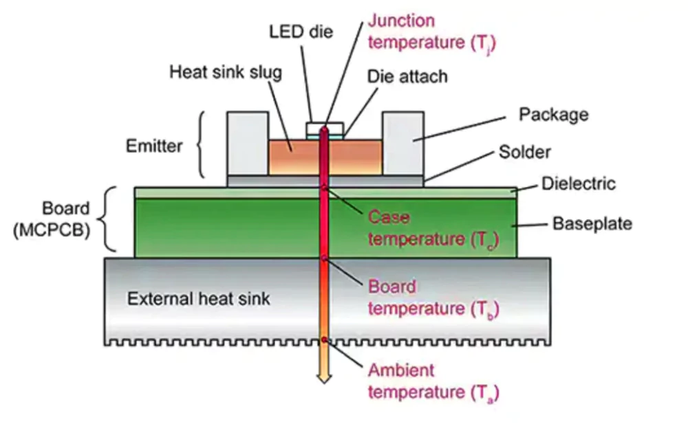
To avoid confusion, it is helpful to distinguish the temperature terminology commonly used in LED thermal design.
| Symbol | Definition | Typical Measurement Location |
|---|---|---|
| Ta | Ambient temperature | Surrounding air |
| Ts | Solder point temperature | LED solder pad |
| Tc | Case temperature | Designated point on LED package |
| Tj | Junction temperature | Inside the LED semiconductor junction (calculated, not directly measured) |
The temperature difference between Tc and Tj depends on the thermal resistance of the LED package, while the temperature difference between Ta and Tc depends on the efficiency of the entire thermal path. Understanding these relationships is fundamental to proper thermal engineering.
One key observation we’ve made is that datasheets typically specify maximum junction temperatures, not recommended operating temperatures. For example, many mainstream manufacturers list absolute maximum junction temperatures between 125°C and 150°C for mid-power LEDs. However, experienced lighting engineers will avoid designing LED lighting modules that approach these limits.
Instead, many commercial LED lighting projects aim to keep junction temperatures below approximately 85–105°C under the most demanding operating conditions. Maintaining this thermal margin helps improve luminous flux maintenance, reduce color shift, and significantly extend product lifespan.
Higntek considers this design margin as important as the highest specifications themselves. Reliability design means leaving sufficient thermal headroom before the product reaches its absolute operating limits.
What Factors Contribute to Achieving Thermal Management of the LED module?
A common misconception I see is that thermal management is simply about adding a bigger heatsink. In reality, this approach can only serve as a remedy when thermal control imbalances are finally discovered; it rarely solves the problem.
When evaluating customer projects, we systematically develop a thermal management engineering plan for LED modules—starting from the LED node, through packaging, PCB, thermal interface materials, electrical design, driver design, heatsink, and heat dissipation paths, ultimately reaching the surrounding air. The flow characteristics of heat are similar to those of electric current; it is always transferred along the path of least thermal resistance, and the weakest link will limit the overall heat dissipation performance. A high-performance aluminum heatsink cannot compensate for a poor PCB layout, just as a high-quality LED will not reach its rated lifespan if the junction temperature is too high.
At Higntek, thermal control begins early in the product design process. We build heat dissipation paths concurrently with electrical, optical, and mechanical design. This reduces development iterations and provides customers with more predictable long-term reliability. The following engineering factors have the greatest impact on the thermal performance of LED modules.
PCB Material and Thermal Design.
The PCB is the first major pathway that removes heat from the LED package. Every material choice directly affects junction temperature. For high-power lighting modules, we usually evaluate several PCB characteristics together instead of considering only the base material.
| Design Factor | Engineering Impact |
|---|---|
| PCB material | Aluminum MCPCB, copper MCPCB, FR4 or ceramic determine thermal conductivity |
| PCB thickness | Affects heat spreading capability and mechanical rigidity |
| Copper thickness | Lower electrical resistance and improve lateral heat spreading |
| Trace width | Reduces current density and localized heating |
| Thermal vias | Transfer heat efficiently between PCB layers |
| Dielectric layer | Lower thermal resistance improves heat transfer to the metal base |
Many designs focus only on selecting an aluminum PCB. However, we have seen modules using the same aluminum substrate perform very differently simply because of copper layout, dielectric quality, and thermal via placement.
During custom projects, we optimize the PCB as a complete thermal platform rather than a simple electrical carrier. Thermal simulations are often performed before prototypes are manufactured to identify localized hot spots early in development.
LED Chip Selection.
Not all LEDs heat up in the same way. Two LEDs operating at the same power can have significantly different junction temperatures due to differences in chip efficiency, size, packaging structure, and thermal resistance.
- Reputable manufacturers such as Nichia, Cree LED, Lumileds, Samsung, and Osram typically publish detailed data on thermal resistance (RθJ-S or RθJ-C), maximum junction temperature, and luminous flux maintenance. These parameters provide engineers with more useful information than simply luminous flux.
- LEDs are available in different sizes, including 2020, 3030, 3535, and 5050. High-power individual chips have a large base area and low thermal resistance, making it easier for heat to be conducted to the heat sink, resulting in high heat dissipation efficiency. Smaller chips have relatively concentrated heat, with high local heat flux density. Integrating multiple small chips can easily lead to “heat concentration,” placing extremely stringent requirements on the overall thermal conductivity of the heat sink.
- Chips come in various packaging forms, including CSP, PCT, EMC, and PPA. When adapting a solution, a comprehensive selection must be made considering cost, hermeticity, thermal resistance, power, and voltage compatibility. For example, CSP chips eliminate gold wires and lead frames, resulting in a very short heat conduction path and significantly reduced package thermal resistance. However, CSP chips require the PCB substrate of the lighting module (such as a high thermal conductivity aluminum substrate or ceramic substrate) to have excellent flatness and thermal conductivity.
In our projects, LED selection is not solely based on brightness or price. We compare luminous efficacy, thermal resistance, forward voltage stability, LM-80 data, and operating temperature characteristics. Sometimes, selecting a more suitable and efficient LED based on the lighting project requirements can significantly reduce overall heat generation, thus eliminating the need for a larger heatsink and improving stability.
Electrical Layout and LED Arrangement.
Heat dissipation depends not only on power consumption but also on the location of power concentration. Insufficient LED spacing leads to thermal congestion, with adjacent LEDs heating each other. Similarly, overly narrow copper traces increase resistance and generate unnecessary heat.
When designing LED modules, we carefully balance the following factors:
- LED spacing.
- Power density.
- Copper wire distribution.
- Current path length.
- Symmetrical heat dissipation.
We design the LED layout to meet customer requirements for brightness and uniformity, resulting in a more even distribution of heat across the entire PCB. This helps reduce peak junction temperature without altering mechanical dimensions.
Driver Design.
The driver contributes to thermal management in two different ways.
First, driver efficiency determines how much electrical power becomes unwanted heat. Modern constant-current drivers commonly achieve efficiencies above 90–95%, while lower-quality drivers may waste significantly more energy as heat.
Second, current regulation directly affects LED junction temperature. Excessive drive current increases lumen output temporarily but also accelerates lumen depreciation and material aging.
Depending on project requirements, we evaluate three common driver architectures.
| Driver Type | Thermal Characteristics | Typical Applications |
|---|---|---|
| Constant Current | Stable LED current and better thermal consistency | Most professional LED modules |
| Constant Voltage | Requires additional current control on PCB | LED strips and distributed lighting |
| DOB (Driver on Board) | Compact design but PCB thermal design becomes more critical | Cost-sensitive integrated lamps |
Rather than selecting a driver independently, we match driver topology with the thermal capability of the entire module.
Heatsink Design.
Effective heatsinks maximize heat transfer while minimizing unnecessary weight, cost, and installation space. Our engineering team evaluates several variables simultaneously:
- Material (aluminum extrusion, die-cast aluminum, copper, graphite)
- Surface area
- Fin thickness
- Fin spacing
- Airflow direction
- Installation orientation
- Natural or forced convection
One lesson we’ve learned through repeated testing is that fin spacing is often overlooked. Dense fins may increase theoretical surface area but can actually reduce natural airflow, trapping warm air between fins and lowering cooling performance. When adapting LED lighting modules for our customers, we don’t aim for the largest heatsink, but rather for the highest overall thermal efficiency within the existing product size range.
Thermal Path Optimization.
The thermal path is the foundation of every reliable LED module. Heat must travel through multiple interfaces before reaching ambient air:
LED Junction → LED Package → Solder Joint → PCB → Thermal Interface Material → Housing or Heatsink → Ambient Air
Every interface introduces thermal resistance. Many projects lose more thermal performance at the contact interfaces than within the heatsink itself. Small air gaps, uneven mounting surfaces, or poor assembly pressure can dramatically increase junction temperature. For this reason, we review the complete thermal resistance network instead of optimizing isolated components.
Thermal Interface Materials (TIM).
Even precision-machined metal surfaces contain microscopic air gaps. Since air has very poor thermal conductivity (approximately 0.026 W/m·K), these tiny voids become thermal bottlenecks. TIMs replace trapped air with materials that transfer heat much more effectively.
Depending on product structure, we commonly select:
| Material | Typical Purpose |
|---|---|
| Thermal grease | Lowest interface thermal resistance |
| Thermal pads | Clean assembly with electrical insulation |
| Thermal adhesive | Permanent mechanical attachment |
| Phase-change materials | High-performance industrial applications |
Material selection is only part of the solution. Correct thickness, mounting pressure, and long-term stability are equally important for maintaining thermal performance throughout the product’s service life.
Active Cooling for High-Power Systems.
Passive cooling is sufficient for most commercial LED modules. However, some high-power applications exceed the practical limits of natural convection. Examples include:
- Stadium lighting
- UV LED systems
- High-power horticulture lighting
- Industrial machine vision
- Medical illumination
These lighting modules may integrate active cooling solutions such as mechanical fans, heat pipes, vapor chambers, or liquid cooling loops. Although active cooling increases modules system complexity, it can reduce junction temperature substantially when passive cooling alone cannot maintain acceptable operating conditions.
At Higntek, we only recommend active cooling after optimizing every passive thermal path first. In many cases, careful PCB, optical, and mechanical redesign achieves the required thermal performance without introducing additional maintenance requirements.
From our engineering experience, excellent thermal management is rarely achieved by improving a single component. Reliable LED modules result from balancing LED selection, PCB design, electrical architecture, thermal interfaces, heatsinks, and system assembly into one integrated solution.
That is why every custom LED module we develop undergoes thermal evaluation as part of the complete product engineering process rather than as a final design check. Solving thermal problems early not only improves reliability and lumen maintenance but also reduces manufacturing cost, simplifies assembly, and shortens product development cycles.
What happens when an LED overheats?
An overheated LED doesn’t just become dimmer—it ages much faster. High temperature accelerates lumen depreciation, reduces efficacy, shifts color, shortens driver life, causes solder fatigue, and in severe cases leads to catastrophic LED or PCB failure. In our projects, preventing excessive junction temperature is often more effective than simply choosing a higher-power LED.
Where does most heat originate in an LED module?
Most heat comes from electrical power that is not converted into light. Even high-efficiency LEDs typically convert only about 35–50% of input power into visible light, while the remaining 50–65% becomes heat. That heat starts at the LED junction and must travel through the package, PCB, thermal interface, and heatsink before reaching the surrounding air.
How should thermal vias be arranged for maximum heat transfer?
Thermal vias work best when placed directly beneath the LED thermal pad in a dense, evenly spaced array. Smaller vias with higher quantity usually transfer heat more effectively than a few large holes, provided solder wicking is controlled. We also optimize via pitch, copper thickness, and filled or plugged vias based on manufacturing cost and thermal targets.
What is thermal crowding in LED arrays?
Thermal crowding happens when multiple LEDs are placed too close together, causing their heat to overlap and create localized hot spots. Even if the average board temperature looks acceptable, these areas can run much hotter than expected. Good spacing, copper layout, and thermal simulation help us avoid hidden reliability issues before production begins.
Is it better to use more LEDs at lower current?
In most lighting applications, yes. Running more LEDs at lower drive current usually improves luminous efficacy, lowers junction temperature, reduces lumen depreciation, and extends system lifetime. Although it increases component count, we often find this approach delivers a better balance between performance, reliability, and total cost of ownership.
Can better thermal management extend LED lifetime?
Absolutely. Lower operating temperatures slow lumen depreciation, reduce material stress, improve driver reliability, and help maintain stable color over time. In our engineering work, thermal management is not just about adding a bigger heatsink—it starts with PCB layout, current distribution, component selection, and validating every design through thermal testing before mass production.
How much does every 10°C increase affect LED lifetime?
A simple rule in LED engineering is: every 10°C increase in junction temperature can reduce LED lifetime by roughly 30–50%. This is not exact for every product, but it follows Arrhenius aging behavior. In real projects, I always treat 10°C as a major design margin, not a small variation, especially for long-hour commercial lighting.
Should you optimize junction temperature or board temperature?
You should always optimize junction temperature (Tj), not just board or heatsink temperature. Board temperature only shows part of the heat path. The real aging and efficiency loss happen at the LED junction. In practice, we use Tc as a control point, but Tj is the true performance driver behind lifetime and color stability.
Why do some LEDs fail even when the heatsink feels cool?
Because “cool heatsink” does not mean low junction temperature. Heat may be trapped inside the LED package due to high thermal resistance or poor PCB design. I’ve seen many failures caused by local hotspots that never appear on the heatsink surface. Thermal bottlenecks inside the LED module are often the real hidden problem.
How can I work on a project with Hignetek?
You can send us your design files or requirements. Our engineering team will provide technical assessment, communication guidance, and a quotation. Once cooperation is confirmed, we will arrange for component procurement, manufacturing, inspection and testing, packaging, and shipping.
Do you support OEM and ODM manufacturing services?
Yes. Higntek provides end-to-end OEM and ODM manufacturing services for outdoor LED modules. We support engineering design, LED PCB assembly, optical layout optimization, testing, and scalable mass production. Many customers come to us not only for manufacturing capacity, but also for practical engineering support during product development and project integration.
Do you accept small-batch orders or only large-scale production?
We support prototyping and small-batch orders to facilitate low-cost testing for our customers. We also support large-scale production and maintain consistent quality control.
How do you ensure quality consistency in large orders?
We ensure quality consistency in large-batch orders through the following methods: raw material inspection upon arrival, die bonding/dispensing/wire bonding inspection during production, AOI/X-ray/functional testing, aging testing, and traceability management.
How quickly can I get samples or quotations?
We usually provide quotations within 24 hours after receiving project details. Sample or prototype lead time depends on customization complexity, material availability, and testing requirements. For faster evaluation, I always suggest sharing application drawings, target dimensions, or lighting requirements early so we can recommend the right module faster.
How do you control product quality during production?
We apply a traceable quality control process across material inspection, SMT production, AOI/X-ray inspection, functional testing, aging tests, waterproof verification, and final performance testing. In our experience, consistent production control matters more than isolated sample performance. That’s why we focus on process stability, thermal consistency, and long-term reliability validation throughout mass production.
What is your typical lead time for prototype and mass production?
Prototypes are typically delivered within 5-7 days. The mass production cycle for standard LED modules is approximately 10-15 days. Specific lead times will vary depending on quantity, specifications, and degree of customization. We typically assess technical parameters and inventory status comprehensively to recommend suitable solutions for our clients.
Engineered LED Modules for Demanding Applications
Full Spectrum LED Modules
DOB LED Modules
Ultra Energy Saving LED Modules
We‘d Like to Hear From You
Tell us about your application, and our engineering team will provide a tailored LED lighting module solution with optimized performance, cost, and reliability.
Start Your Custom LED Module Solution
On-Time Delivery 99.38%
Consistent production & reliable global delivery
End-to-End Engineering Support
From design optimization to production guidance
3-Day Rapid Prototyping
Fast sampling to accelerate product validation
100% Quality Inspection
Full testing ensures stable and reliable performance
