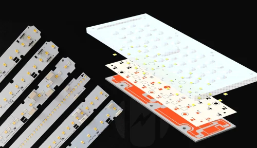
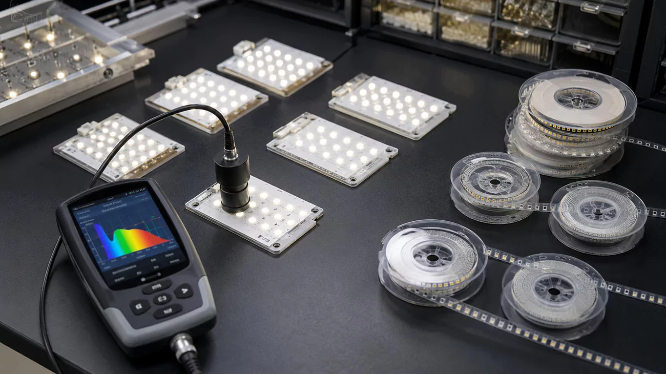
LED Binning for Color Consistency and Module Design.

LED Binning Choices for Custom LED Module Engineering

LED binning is the process of measuring LEDs and grouping them by defined characteristics such as color, luminous flux, or forward voltage. It reduces variation at the component input, but it does not by itself guarantee uniform color from a finished LED module or lighting fixture. Optical mixing, LED spacing, drive current, thermal conditions, calibration where applicable, and production-lot control still shape the result.
We prioritize a traceable bin specification: the measured range, test condition and reel identification must agree with the incoming-inspection record. That gives repeat orders a defined matching target. Send us the target CCT, chromaticity or wavelength, color tolerance, optical layout and operating conditions so our Higntek engineering team can develop the module around a traceable source specification.

What is LED Binning?

LED binning is the process of measuring and sorting LEDs into defined color, luminous-flux and forward-voltage ranges. Color bins define a region in chromaticity space for white LEDs or a wavelength interval for colored LEDs; flux bins define a lumen interval; and forward-voltage bins define a voltage interval at a stated current. Small differences in semiconductor growth, phosphor conversion and assembly during the manufacturing process produce variation even within one product family. Binning records that variation so the module designer can specify which groups are acceptable.

Color grading.

Color grading gives us a practical starting point for selecting the appearance of an LED module. For white-light specification, we use four broad CCT categories: warm, neutral, cool and extra cool. These categories help us translate the intended lighting effect into a source-selection range before narrowing the target color point.

White-light categoryCCT range
Warm white2700 K to 3500 K
Neutral white3500 K to 5000 K
Cool white5000 K to 7000 K
Extra-cool white7000 K to 10000 K

We use the category to establish the design direction, then specify the exact target CCT within it. For a warmer appearance, we start with the warm-white range; for a more neutral or cooler appearance, we move to the corresponding range. A boundary value such as 3500 K is recorded as an exact target rather than left to the category label. This gives our LED selection and optical development a clearer brief than a request for warm or cool light alone.
Within the selected category, we prioritize chromaticity and the allowed color spread for modules that will be viewed together. A 3000 K and a 3500 K source both fall within the warm-white range, but that does not make them interchangeable for a matching installation. We recommend defining the target coordinates, SDCM tolerance and Duv limit where tint matters, then comparing the supplier’s bin regions with that requirement. Groups extending outside the accepted region need a narrower selection or additional screening. For colored LEDs, the equivalent selection uses the specified wavelength metric and its lower and upper limits.
Set the required CRI before source selection as well. Matching CCT or chromaticity does not establish how faithfully the source renders object colors, and CRI is a separate lighting requirement rather than a color-bin interval.
For adjacent modules and later replacements, we also recommend retaining the approved bin combination and comparing representative assemblies in the intended optics. Two sources can meet the same target-relative tolerance yet differ from each other. Carrying the color specification into the layout and prototype checks connects our source selection to the consistency the installation needs.

Luminous-flux grading assigns measured lumen output to supplier-defined intervals at a declared current, temperature and optical test condition. A measurement method can make readings comparable under stated conditions, but it does not create universal component flux-bin thresholds; the interval belongs to the selected product and its stated test condition.
We select that interval from the module’s output budget, checking its lower limit against the required light output and its upper limit where channel or module balance matters. In the assumed 100 to 110 lm group used in the coding example, a 105 lm reading falls inside the interval while 98 lm and 112 lm fall outside it under the same test conditions. The supplier’s specification controls how readings on a shared boundary between adjacent groups are treated. A higher flux group earns its place when it meets the assembled output target within the power, thermal and optical budget, not because bin rank alone establishes efficacy or quality.

Flux-grading elementWhat the grading definesWhat the supplier must documentWhat we verify at module level
Measured propertyLuminous flux in lumens at the declared drive currentThe bin code and its lower and upper flux valuesAssembled output against the module’s lumen budget
Test conditionsThe current, temperature reference and optical condition at which the reading is validThe declared current, temperature reference and optical test conditionThat the comparison uses the same conditions as the module’s operating point
Boundary treatmentHow a reading that falls on a shared boundary between adjacent groups is assignedThe product’s rule for boundary and permissible combinationsThat the purchased grouping is unambiguous for the order
TraceabilityWhich production group the measured interval belongs toDatasheet revision, bin code and lot or reel identityIncoming inspection and later replacement matching

Forward-voltage grading assigns Vf readings to supplier-defined intervals at a declared current and temperature. No universal Vf-bin ladder applies across LED products; the selected interval is a product characteristic, not a quality score. We prioritize the full voltage range when selecting LEDs for a module, because the selected series count must work with the external driver’s operating range.
In the illustrative 3.0 to 3.2 V group, ten series-connected LEDs imply 30 to 32 V at the stated test point, before allowing for operating-temperature variation and other circuit requirements. That range gives a concrete basis for comparing source groups with the driver interface, rather than comparing nominal voltages alone. Parallel paths also need suitable current regulation; a narrow Vf group does not by itself establish balanced current sharing or higher quality.

Vf-grading elementWhat the grading definesWhat the supplier must documentWhat we verify at module level
Measured propertyForward voltage in volts at the declared drive currentThe bin code and its lower and upper Vf valuesSeries-string voltage against the driver’s operating range
Test conditionsThe current and temperature reference at which the reading is validThe declared current and temperature referenceThat headroom is checked across the full selected interval, not the nominal value
Boundary treatmentHow a reading that falls on a shared boundary between adjacent groups is assignedThe product’s rule for boundary and permissible combinationsThat parallel branches still receive suitable current regulation
TraceabilityWhich production group the measured interval belongs toDatasheet revision, bin code and lot or reel identityIncoming inspection and later replacement matching

Temperature condition, or hot binning, identifies the thermal point at which color, flux and Vf are characterized. It is a measurement condition rather than a fourth universal grade. We recommend writing both the source test condition and the intended module verification condition into the specification. A room-temperature bin record provides one reference point; a module intended to run warm also needs its output and color evaluated after reaching its specified operating state. A source group is suitable when it supports the module’s acceptance limits at that working condition, not merely when its cold measurement looks favorable. Maximum rated temperature remains a separate limit. Hot binning changes the characterization point; it does not create a heat-resistance ranking or remove module thermal verification. After we complete the LED lighting module prototyping, we will also conduct thermal verification on the module.

Temperature-grading elementWhat the grading definesWhat the supplier must documentWhat we verify at module level
Measured propertyWhich of color, flux or Vf is characterized at the stated temperatureThe property covered by the hot or standard recordOutput and color at the module’s intended operating state
Reference pointThe thermal point the reading is tied toThe stated junction, pad, case or specified reference temperatureThat the module’s working condition is compared against the same reference
Test postureWhether the record is standard-condition, hot-tested or hot-targetedThe declared posture of the test, not a temperature classThat the choice matches how the module will actually run
Separate limitMaximum rated operating temperature, kept independent of the bin recordThe rated maximum where the datasheet states oneThat thermal design is verified separately from bin selection

ANSI C78.377 specifies recommended chromaticity ranges for general lighting with solid-state lighting products, providing a common reference for communicating white-light color. Component selection still requires the LED manufacturer’s bin definitions. A bin code number structure can combine letters and numbers identifying flux, color and voltage groups; their order and meaning depend on the product’s code key. An LED binning chart maps those codes to measured ranges or chromaticity regions. Read the chart together with its test conditions and datasheet revision, then decode each field separately, as the example below illustrates.
The same LED has separate color, flux and voltage classifications because each describes a different measured property. For white LEDs, nominal CCT identifies the broad color target, while chromaticity-bin coordinates define the permitted region more precisely. A product model identifies the selected LED family and configuration; the reel bin code identifies the measured groups assigned to that shipment. During the module development process, we meticulously review all identification data and maintain records of LED component coding conventions and specification versions. This ensures that if any design changes are required, they can be verified against the original constraints and standards.
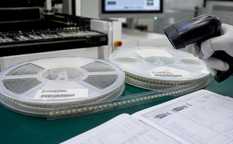
Inspecting LED reel labels and datasheets

Information to identify

What it tells the project

What still needs verification

Color bin

The allowed color region or wavelength group for the selected source

CCT, chromaticity coordinates or wavelength, Duv where relevant, and the target tolerance

Flux bin

The component output group under the stated test condition

LED count, drive current, thermal condition, optics, and final module output

Forward-voltage bin

The electrical range at the stated current and temperature

String architecture, driver range, current balance, and operating headroom

Lot and reel identity

Which production group supplied the components

Replenishment matching, spare allocation, and incoming inspection records

Example: Consider a fictional product, EXAMPLE-LED-A, with an illustrative reel code F2-C3-V1. Assume its code key defines F2 as 100 to 110 lm, C3 as a CCT band of 3950 to 4050 K, and V1 as 3.0 to 3.2 V, all at a test current of 350 mA and a junction temperature of 25°C. The reel code therefore identifies the permitted light-output, color-temperature and voltage ranges for this hypothetical shipment. Every code and value here is assumed for explanation. In an actual order, the supplier’s specification must also define the chromaticity region because a CCT band alone does not fully specify color matching. Use the supplied code key and test conditions to interpret the reel, then verify the assembled module at its intended operating point.

How Does LED Binning Affect Color Consistency in Lighting Fixtures?

White LEDs require a CCT target plus chromaticity coordinates and an accepted tolerance, while colored channels require a stated wavelength metric and interval. LED color binning narrows the source-color differences that a fixture must blend. For colored LEDs, violet, blue, green, yellow, orange and red occupy progressively longer parts of the visible spectrum; perceived color changes continuously across their boundaries.

Visible color

Approximate wavelength range

Violet

380 to 450 nm

Blue

450 to 495 nm

Green

495 to 570 nm

Yellow

570 to 590 nm

Orange

590 to 620 nm

Red

620 to 750 nm

These broad color bands are not LED bin widths. A colored LED bin covers a much narrower product-specific interval, commonly expressed by dominant wavelength for perceived hue. White LEDs emit a combination of wavelengths, so their matching specification uses CCT and chromaticity rather than a single wavelength. Duv describes the tint offset from the blackbody locus, helping distinguish sources with similar CCT but different greenish or pinkish appearance.
Multi-LED mixing combines each source’s spectrum in proportions set by its output and the optical path. LEDs with different color points can produce a useful average when their light overlaps thoroughly. That average does not describe every position across the beam: individual sources can remain visible through a shallow diffuser or create colored fringes where their beams do not overlap. For RGB or tunable-white modules, channel-output differences also change the mixed color point.

Mixed-bin risk appears when the composition changes between boards, reels or replacement batches. Matching nominal CCT alone does not keep those mixtures identical. A replacement module can therefore look different from a neighboring module even though both carry the same CCT label. We recommend specifying the acceptable color region and replenishment-matching rule together, then retaining the bin and lot records for later comparison.
Array uniformity concerns the spatial distribution of color across a board, along a linear run and across the illuminated surface. Clustering LEDs from one edge of the permitted color region can create a local tint patch even when the module’s overall average meets its target. Distributing selected LEDs consistently and providing adequate optical overlap reduces this risk. Representative samples should be checked at the installed distance and angle, including board joints and beam edges.
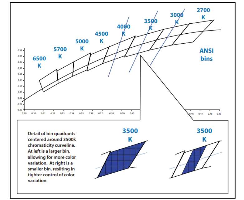
Two 3500K LED luminaires exhibit a subtle color difference
FAQ

What Is the Relationship Between SDCM and MacAdam Ellipse?

A MacAdam ellipse describes a local color-matching region around a chromaticity target. SDCM expresses the scale of that region in steps. A smaller step count means a tighter target-relative tolerance, provided the same target and definition are used. It does not by itself specify brightness, CRI or the appearance of every pair of fixtures.

Lower SDCM means tighter color matching, not automatically better overall lighting. It can justify extra cost for adjacent beams or color-critical surfaces, while wider tolerances may suit thoroughly mixed or separated sources. We recommend matching the tolerance to the visual task and sample results, alongside CRI, optics and operating conditions. At Higntek, we can tailor the LED selection and custom module design to your application, color tolerance and budget.

Need Help Choosing the Right LED Bin?

Not sure which flux, color, voltage or SDCM specification fits your LED module project? Share your target CCT, CRI, output and application with our engineers for a practical recommendation.

On-Time Delivery 99.38%

Consistent production & reliable global delivery

End-to-End Engineering Support

From design optimization to production guidance

3-Day Rapid Prototyping

Fast sampling to accelerate product validation

100% Quality Inspection

Full testing ensures stable and reliable performance

Higntek-icon logo

Discuss LED module project specifications with professional engineers.

Pre-Engineering Inquiry