LED Module DOB Technology Principles, Components & Driver Comparison.

How DOB LED Technology Works

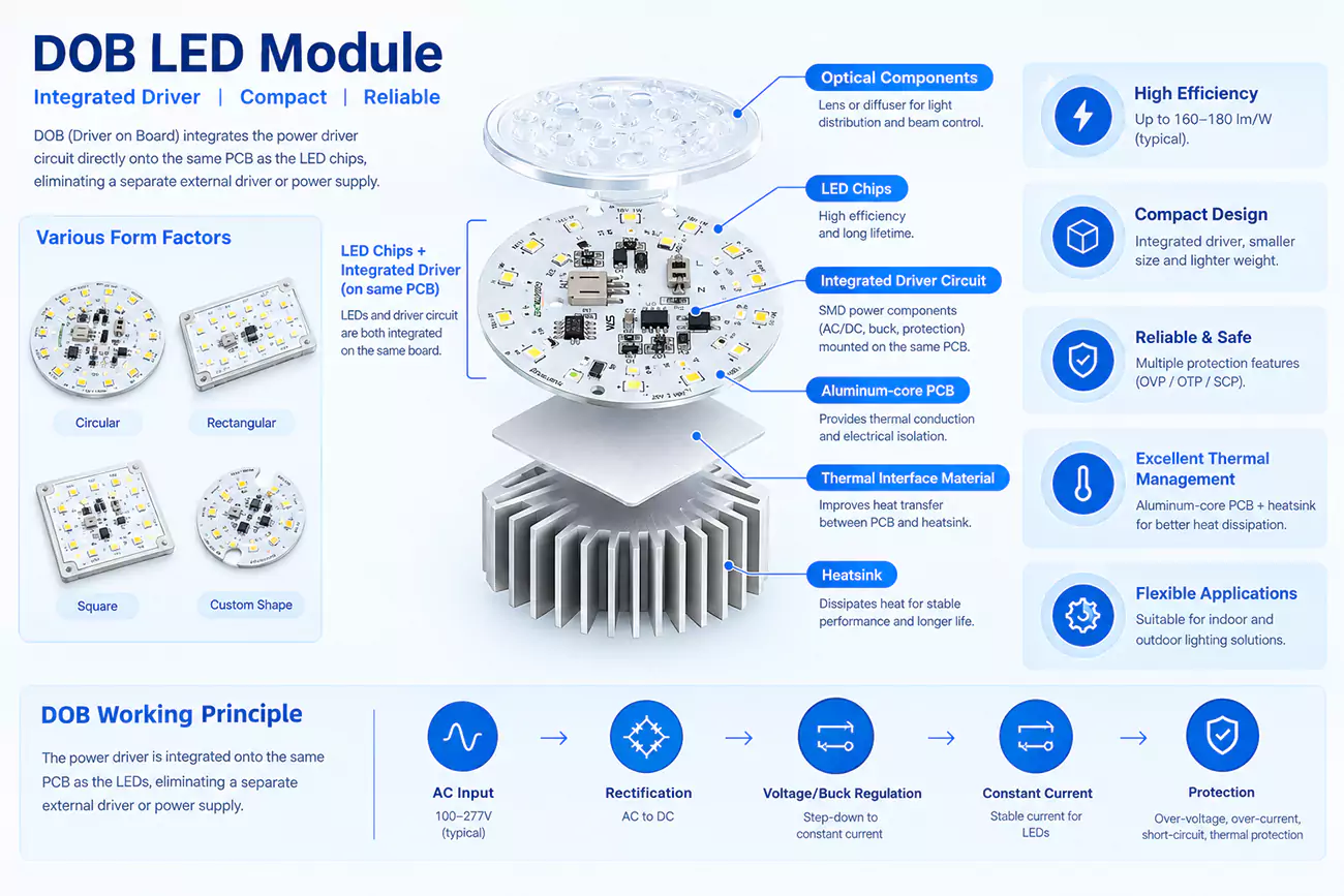
DOB technology, or Driver on Board, places the LED driver circuitry and LED array together on the same PCB rather than relying on a separate external driver. This integrated approach is widely used in compact DOB LED lights where board space, component layout and overall luminaire size matter.
DOB LED products are sometimes called driverless LEDs, but that description can cause confusion. The driver function is still there; it is simply integrated into the board. In practice, DOB is also not one fixed circuit design. Linear, switching, isolated and non-isolated architectures all exist, and each behaves differently once efficiency, power quality, safety and thermal performance become part of the design.
For lighting brands and engineers, that distinction matters. Two DOB LED modules may look similar on paper yet perform very differently inside the finished luminaire. What matters is how the DOB LED driver, LED array and board design work together to meet the project’s electrical, thermal and lifetime requirements.

What Is DOB Technology in LED Lighting?

DOB technology, or the Driver on Board, integrates the LED driver circuitry directly onto the same PCB as the LED array. Instead of treating the light source and power electronics as two separate assemblies, a DOB LED module brings them together at board level.
That compact structure is one of DOB’s most recognizable characteristics. Fewer connections between a separate driver and LED board can greatly simplify the internal layout of space-sensitive lamps and luminaires. But compactness is only part of the engineering story. Once the driver moves onto the board, electrical design, LED configuration, protection and thermal behavior become more closely linked. Changing the LED string, input voltage or driver scheme can affect the rest of the module rather than just one isolated component.

The word “driverless” can therefore be confusing. A DOB LED has not stopped needing a driver function. The rectification and current-control functions are still there; they are simply integrated onto the board. This distinction matters when evaluating a DOB LED light, because LEDs still need controlled current even when there is no external driver box.

There is another detail worth getting right from the beginning. DOB technology is an integration architecture, not one fixed power-conversion topology. Many AC DOB LED designs use non-isolated linear regulation, including high-voltage and segmented linear approaches. Switching DOB designs also exist, and isolation can be added where the electrical and safety requirements call for it. So DOB, linear and non-isolated should not be treated as the interchangeable terms.
This is useful when comparing two DOB boards that look nearly identical. The PCB dimensions and rated wattage may match, but their electrical behavior can differ because they use different LED-string voltages, current-regulation methods, isolation strategies or DOB LED driver ICs. For us, the DOB label is only the starting point. The circuit, LED load and PCB layout still have to be engineered around the finished lighting application.

Besides, the DOB’s clearest advantages come from compact integration, while its main limitations are engineering trade-offs created by bringing the LED array and driver electronics into the same board-level system.

AdvantagesEngineering Trade-offs
Compact module architectureLEDs and driver electronics share a closer thermal environment
Fewer separate connectionsModule-level servicing can be less independent
Simpler internal fixture layoutSurge, flicker and power quality depend on the onboard circuit design
Potentially fewer separate assembliesPCB layout, protection and thermal design become more critical

How Does DOB Technology Work in LED Modules?

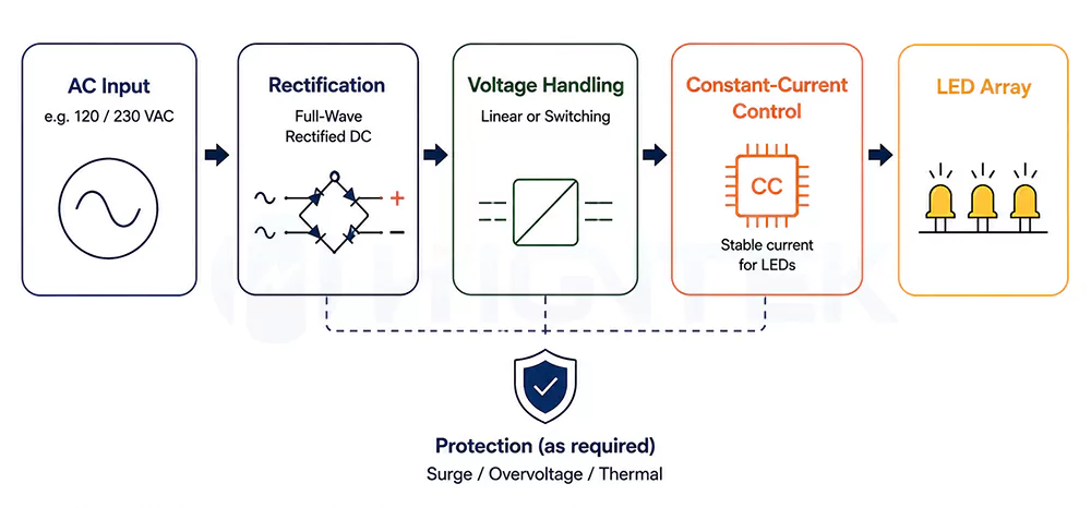
An AC DOB LED module generally follows five stages – the AC input, rectification, voltage handling, constant-current regulation and protection. The sequence sounds very simple, but one point causes a lot of confusion that not every DOB circuit “steps down” the mains voltage in the same way.

StageWhat happensWhat it means
AC inputMains power enters the module PCBThe board must match the intended input-voltage range
RectificationAC becomes full-wave rectified DCCurrent is presented to the LED circuit with one polarity
Voltage handlingThe circuit brings the available line voltage into a usable relationship with the LED loadLinear and switching DOB architectures handle this differently
Constant-current regulationThe DOB LED driver IC controls current through the LED arrayStable current keeps the LEDs within their intended operating range
ProtectionThe design deals with electrical or thermal abnormalitiesProtection may address surges, overvoltage, excessive temperature or LED faults

AC input and rectification come first. In an AC DOB LED, mains voltage reaches the board directly. A bridge rectifier then converts the alternating waveform into full-wave rectified DC. That does not mean the board suddenly has the smooth and low-voltage DC output we associate with a conventional low-voltage supply. Sequential linear LED driver reference designs, for instance, can operate directly from a 230 VAC line after rectification and control a long high-voltage LED string without a conventional magnetic conversion stage.
The voltage numbers make the reason easier for us to see. A 120 VAC sine wave has a peak of roughly 170 V, while 230 VAC reaches roughly 325 V. This is why many linear AC DOB designs work with relatively long series LED strings rather than treating the board like a 12 V or 24 V DOB LED strip.

The next stage is better described as voltage handling than just simply “step-down.” In a high-voltage linear DOB, the combined forward voltage of the LED string is designed around the rectified mains waveform, while the linear regulator controls the current and deals with the remaining voltage needed for regulation.

  • Segmented linear DOB takes a more dynamic approach. The LED array is divided into taps or sections, and different sections conduct as the instantaneous rectified voltage rises and falls. Published sequential-linear designs use four or six LED taps and switch the regulators at different points in the AC cycle. This makes better use of the changing input waveform while keeping LED current controlled.
  • A switching DOB handles voltage differently again. Instead of relying mainly on the relationship between the mains waveform and a high-voltage LED string, a switching stage actively transfers and converts energy. Non-isolated buck and buck-boost architectures are both established approaches in offline LED driving. One non-isolated buck reference design, for example, regulates 130 mA ±2.5% into a 15-21 LED load, and illustrating how a switching stage can create a controlled LED output from a much higher AC input.

Whichever DOB architecture we work with, one requirement does not change that the LEDs still need controlled current. LED forward voltage varies with device characteristics and operating temperature, so applying an uncontrolled voltage can push current beyond the intended operating point. The DOB LED driver IC or current-regulation circuit keeps the LED array around its target current as line and load conditions change. Offline LED driver technology is specifically designed around accurate constant-current output for this reason.

Protection closes the loop. Depending on the circuit and application, a DOB LED driver may include transient or surge protection, overvoltage and overcurrent protection, LED open/short protection, temperature sensing, thermal foldback or thermal shutdown. These are design choices rather than a checklist every DOB module automatically contains. Driver designs show both optional transient-protection components in simple sequential-linear circuits and integrated electrical or thermal protection in more sophisticated driver ICs.
How Does DOB Technology Work in LED Modules

In our DOB module development, we therefore look at the LED array, driver scheme and PCB layout together rather than treating the onboard driver as a last-minute addition. LED forward-voltage windows need to match the regulation range, PCB traces need to carry the rated current reliably, and the selected driver needs enough electrical and thermal margin for the intended fixture. That same integrated approach continues through prototype validation, SMT/PCBA production and testing in our custom LED module process.

What Are the Main Components of a DOB LED Module?

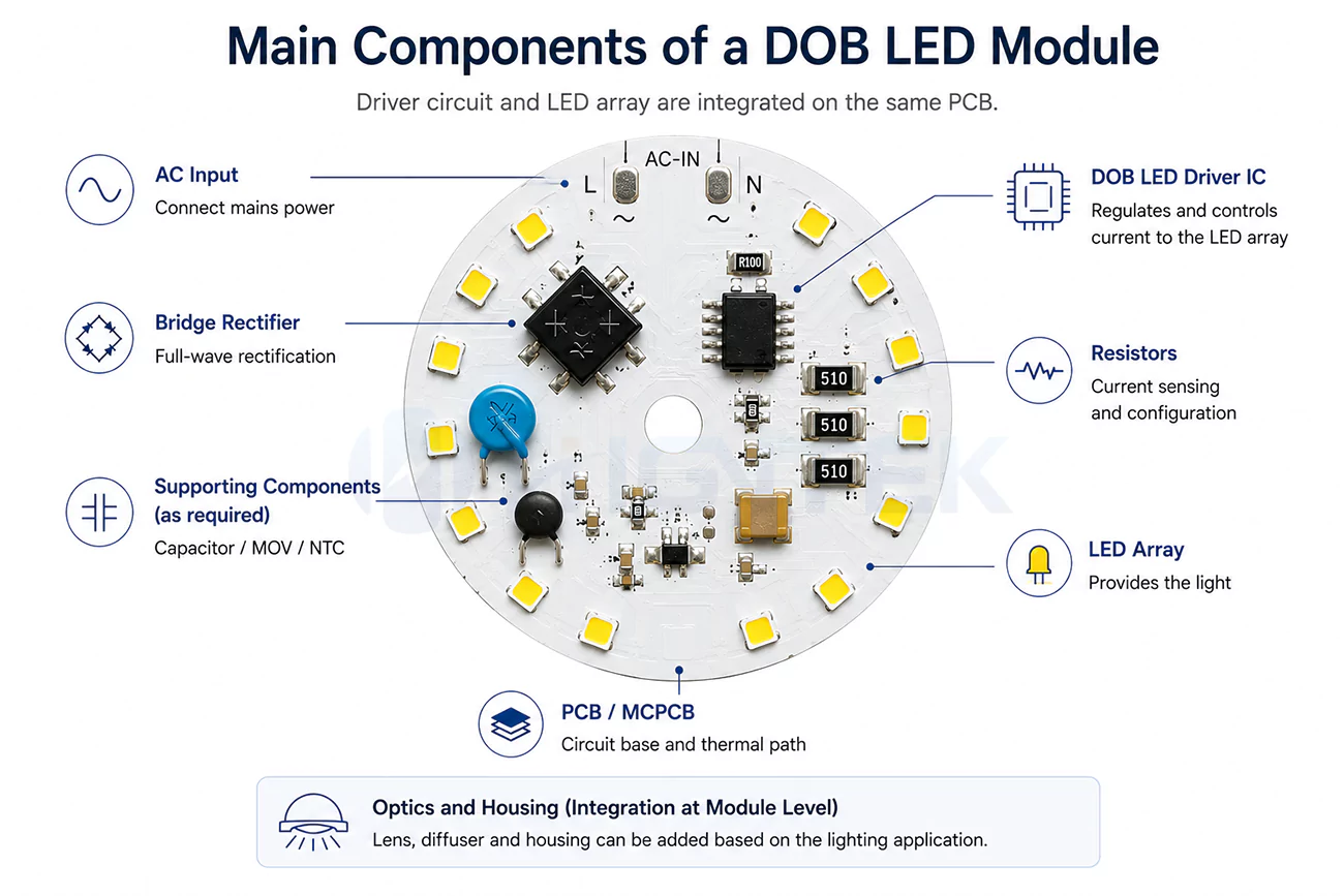
A DOB LED module is not defined by one special component. It is a board-level system that brings the PCB, LED source, LED array, rectification stage, current-control circuit, supporting protection parts, optics and mechanical structure into one module.
There is no fixed DOB BOM. A simple linear DOB circuit and a switching DOB circuit may use very different components even when the finished boards look similar. The useful question is whether each part matches the same electrical load, thermal condition and lighting application.

Component GroupTypical PartsMain Role
PCB and substrateAluminum MCPCB, copper-based PCB, FR-4 for lower-power use, copper layer, dielectric layerCarries the circuit, supports heat spreading and defines the board layout
LED source2835, 3030, 3535, 5050 packages across different LED seriesProduces light and forms the electrical load
LED arrayLED strings, series/parallel/tapped arrangementsSets the load voltage, current path and light-source distribution
Input and driver sectionBridge rectifier, DOB LED driver IC, current-regulation circuit, resistors, MOSFETs or inductors where requiredRectifies the AC input and controls LED current
Supporting and protection partsCapacitors, MOV, NTC, TVS, fuse or protective resistor where requiredHandles filtering, surge, inrush current, sensing or abnormal conditions
Optical and mechanical partsLens, diffuser, reflector, housing, connectors, mounting structureShapes the light and integrates the board into the finished fixture
PCB Design and Substrate.

The PCB is the base of the DOB module. It carries the LED array and onboard driver circuit, sets the component layout and becomes part of the heat path inside the luminaire.
FR-4 can still be used in lower-power or cost-sensitive designs, but it is rarely the right choice when a DOB module has a meaningful thermal load. Once heat density rises, aluminum MCPCB or copper-based PCB structures usually give the module a stronger heat path. And the FR-4 is usually around 0.3-0.4 W/m·K, aluminum MCPCB about 1.0-3.0 W/m·K, and copper-based or higher-performance MCPCB solutions about 3.0-8.0 W/m·K.
Board thickness, copper thickness and thermal conductivity should be treated as separate decisions. Board thickness affects rigidity and fixture fit. Copper thickness affects current carrying, voltage drop and lateral heat spreading; common LED module copper weights may range from 0.5 oz to 2 oz, roughly 18 μm to 70 μm. Thermal conductivity describes how efficiently the substrate and dielectric structure move heat away from the LEDs and driver area.

This is where PCB engineering becomes more than choosing a material name. Copper distribution, trace width, dielectric quality, component spacing, thermal vias, surface treatment and board shape all affect whether the DOB module can carry current, control heat and fit the customer’s luminaire. A compact round ceiling-light module and a long linear module may need different combinations of board thickness, copper weight and thermal conductivity even when their rated power is similar.

LED Packages and Light-Source Selection.

In project discussions, people may call this part the LED chip. At module level, the more useful question is which LED package, series and electrical specification should be selected for the application.
Our current LED portfolio covers seven series, with package specification options including 2835, 3030, 3535 and 5050. The 2835 platform is commonly used for compact mid-power indoor applications such as tubes, panels and soft-strip style modules. The 3030 platform fits many outdoor and industrial lighting needs, including street, tunnel and industrial applications. The 3535 ceramic package is used where thermal performance is more demanding, such as high-bay, floodlight and stage applications. The 5050 platform covers high-power flagship and special lighting uses. LED size specifications serve only as an initial screening criterion; actual customization projects require selecting components based on specific application needs, voltage, current, and other factors. That range allows the LED source to be matched to different application needs instead of forcing one package type into every module.

For a DOB project, LED selection is not only about luminous efficacy. CCT, CRI, color consistency, forward voltage, operating current, power level and package thermal behavior all affect how the LED source works with the onboard driver. For example, indoor lighting may call for voltage options such as 3V-18V, while outdoor applications often work around 6V-24V options. Higher-power special applications may need a different electrical window again.
The goal is not simply to choose the brightest LED on paper. A high-efficacy source is valuable only when its voltage, current, thermal behavior and optical output fit the DOB circuit and the finished fixture.

LED Array and Driver Load.

The LED array is the way selected LEDs are connected and arranged on the PCB. In a DOB module, it is both the light-emitting surface and the electrical load controlled by the onboard driver.
For the driver circuit, the key factors are the total LED-string voltage and target current. Changing the LED count, series-parallel arrangement or tapped structure changes the load that the DOB driver has to regulate. This is why LED array design cannot be separated from driver matching.
Array layout also affects light uniformity and local heat concentration, but those details belong to the optical and thermal design stages. In this component section, the main point is simpler: the LED array must match the driver’s regulation range and the fixture’s required light output.

Bridge Rectifier.

The bridge rectifier is part of the AC input stage in many AC DOB modules. Its basic job is to turn the alternating polarity of AC input into full-wave rectified DC before the current-regulation circuit controls the LED load.
This part is often misunderstood. A bridge rectifier is not a complete LED driver. It does not regulate current, and it does not create the smooth low-voltage DC output associated with a conventional external power supply. It simply prepares the input waveform so the following DOB driver circuit can work with one current direction.
For module design, the rectifier still needs careful selection. Its voltage rating, current rating, package, losses and operating margin must fit the intended mains range and module power. Placement also matters because it sits near the input side of the circuit and can add its own heat load to a compact DOB board.

DOB LED Driver IC and Current Regulation.

The DOB LED driver IC is the main control device in many onboard-driver designs. Its job is to keep the LED array near the intended current as input voltage, LED forward voltage and temperature conditions change.
This is also where the “driverless LED” label can mislead buyers. The driver function has not disappeared; it has moved onto the LED board. In many linear DOB designs, the constant-current function is already built into the driver IC or current-regulation circuit, so a separate “constant-current chip” is not always another independent component.

The right driver solution depends on the architecture. A high-voltage linear DOB, segmented linear DOB and switching DOB may use different control methods and different supporting parts. A switching design may also require MOSFETs, inductors, diodes and additional capacitors, while a simpler linear design may use a smaller component set.
For Higntek, our value is not in manufacturing the driver IC itself. The driver IC is normally a sourced electronic component. The engineering value is in matching the driver solution to the LED array, designing the surrounding circuit and PCB layout, validating the prototype and controlling production consistency.

Capacitors, MOVs and NTCs.

Capacitors, MOVs and NTC thermistors can solve different electrical problems, and a DOB LED board does not automatically need all three.

  • A capacitor may support filtering, ripple control or energy storage, and switching circuits often rely on capacitors as part of the power-conversion stage. On the other hand, some simple sequential-linear circuits operate without capacitors at all.
  • A MOV, or the metal oxide varistor, is a protection device rather than a current regulator. It responds to transient overvoltage and is commonly used to protect electronic circuits from surge events. Its resistance drops as the applied voltage rises beyond its normal range, allowing the device to clamp the overvoltage.
  • An NTC thermistor can serve two quite different purposes. Placed in the input path, an NTC can limit the high inrush current that occurs when a circuit is first powered. NTC devices are also widely used for temperature sensing because their resistance decreases as temperature rises.

So an NTC on a BOM does not tell the whole story. Its location and surrounding circuit show whether it is dealing with startup current or temperature. This is a useful way to judge DOB components in general. More parts do not automatically mean a better board. Each component should have a clear job that matches the electrical and protection requirements of the product.

Optical Elements.

Lenses, diffusers and reflectors determine how the light leaving the LED array is distributed in the finished application.
A lens controls beam direction and shape. A diffuser blends individual LED sources and improves uniformity. A reflector redirects light through the required optical path. Their selection depends on the beam target, fixture geometry, LED package, LED array and available optical distance.
Our optical development covers LED and lens matching, diffuser design, optical simulation and photometric validation. Current solutions include more than a dozen beam-angle options from 15° to 120°, with custom optics available where a standard distribution does not fit the application.

Housing and Mechanical Integration.

A bare DOB PCBA is not necessarily a finished DOB light engine. Some projects stop at the populated board. Others require connectors, wiring, lenses or mechanical structures to be assembled with the PCB before the module reaches the customer’s luminaire production line.
The required level of integration determines details such as module dimensions, mounting points, cable exits, connectors, optical-part retention and service access. Our scope can extend from PCB design and SMT assembly into wiring, optical and mechanical integration according to the product requirements.
Key components of the DOB LED module

A good DOB LED module is not defined by having the longest component list. The PCB, LED source, LED array, driver circuit, protection parts, optics and mechanical structure need to match the same product requirement. That is what makes the components work as a module rather than simply coexist on one board.
What Is the Difference Between DOB and Traditional LED Drivers?

The core difference between DOB (Driver-on-Board) and traditional LED drivers lies in the placement of the driver circuitry and the method of power management. A DOB LED module places the driver circuitry directly on the LED PCB. A traditional external-driver system keeps the power unit as a separate assembly connected to the LED module, even when that driver is mounted inside the luminaire housing.
This one structural difference changes several practical decisions – fixture depth, wiring, thermal layout, electrical protection, dimming interface, servicing method and total system cost. DOB is usually selected for compact, integrated light engines. External drivers are often preferred when the product needs more control flexibility, easier driver replacement or a more separated power architecture.

Compact Integration vs. Separate Driver Space.

DOB is usually the more compact architecture. Because the LED array and driver circuit share one board, the fixture no longer needs a separate driver enclosure or a driver-to-board connection inside the lamp body. This can make the light engine cleaner, thinner and easier to assemble. That matters in products where internal space is tight, such as shallow ceiling lights, compact downlights and other fixtures with limited housing depth.

In one residential lighting project, a European customer was developing a 15 W ceiling light. The original LED board plus separate driver arrangement pushed the internal light-engine depth to about 30 mm. After we redesigned the module around an AC DOB solution for fixed-output operation, the depth was reduced to about 24 mm. That is roughly a 20% reduction in light-engine depth.
The reason DOB worked in that case was not simply “fewer parts.” The product had limited internal height, fixed-output operation and no requirement for DALI control or independently replaceable control gear. The mechanical requirement and electrical requirement pointed in the same direction. External drivers take more space, but that separation also brings value. The driver can be selected, positioned or replaced separately from the LED module. For products that need several power versions, different control interfaces or easier maintenance, that extra space may be worth it.

Electrical Isolation and Safety Design.

DOB and external-driver systems can both be isolated or non-isolated. The driver location alone does not decide the safety level. What matters is whether the power architecture provides galvanic separation between the mains input and the LED side.

Many compact AC DOB designs are non-isolated. In these products, the LED circuit may remain electrically referenced to the mains. That means the PCB spacing, insulation, connectors, enclosure and accessible conductive parts all have to be considered as part of the finished luminaire design.
An external driver often gives designers more room to package the isolation barrier inside a separate power unit. This can be convenient for products where user access, replacement, installation environment or certification requirements make separation valuable. But an external driver is not automatically safe by label alone. The wiring, driver mounting, housing and service access still need to match the safety structure of the complete product.

When developing LED lighting module solutions for clients, our primary focus is not merely on whether DOB or an external driver is safer, but rather on which architecture best aligns with the luminaire’s insulation structure, operating conditions, and target market requirements.

Thermal Relationship.

DOB places the LED array and driver electronics in the same thermal environment. This is the main thermal trade-off. The PCB and housing need to manage heat from both the light source and the onboard power circuit within one compact structure.
An external driver makes physical separation easier. The driver can sit away from the hottest LED area, or even in a separate driver compartment. This can be useful in higher-power, long-hour or thermally sensitive fixtures where the product has enough space for a separated power unit.

That does not mean every DOB LED runs hotter or has a shorter life. A DOB module with suitable LED loading, PCB substrate, copper design and housing contact can still operate reliably. At the same time, an external driver can also fail early if it is placed in a hot, poorly ventilated area.
The difference is in thermal responsibility. DOB asks the PCB and fixture structure to handle LED heat and driver heat together. External-driver systems give the product team more physical separation, but the full luminaire still needs proper thermal planning.

Driver Design Space, Power Quality and Flicker.

Power quality and flicker are not decided by the words DOB or external driver. They are decided by the driver circuit, available design space and performance target.
In a DOB module, current regulation, filtering, surge protection and ripple control have to fit on or around the LED PCB. This can work well for compact fixed-output products, but the circuit space is more limited. If the project requires high power factor, lower THD, low flicker, stronger surge performance or wider input conditions, those targets must be considered early in the DOB circuit design.
An external driver usually gives more room for a dedicated power stage. The power unit can carry more complete filtering, power-factor correction, dimming control and protection circuitry, while the LED board focuses on the light source, optical structure and heat path. This is one reason external drivers remain common in commercial, architectural and controllable lighting systems.
When electrical performance goals are clearly defined, the DOB solution can balance high efficiency with a compact structure; while when projects involve higher power quality requirements or more complex control functions, external drivers often provide more circuit space and configuration flexibility.

Dimming and Control.

DOB can support dimming, but the control method has to be planned into the onboard circuit. For a fixed-output lamp, this is often straightforward. The module can stay compact, and the driver function can remain integrated with the LED board.
When the project requires DALI, 0-10 V, PWM, TRIAC dimming, sensors or connected lighting functions, the choice becomes more specific. The DOB board needs the right control circuit, wiring interface and PCB area for that control method.
External drivers usually give more ready-made control options. Many driver families are already available with different dimming interfaces, output ranges and market certifications. That can be useful when one luminaire platform needs different driver versions for different projects.
In our module work, we normally confirm the control requirement before choosing the architecture. If the product is a compact fixed-output lamp, DOB may be the cleaner direction. If the product needs complex controls, field configuration or multiple driver options, an external driver may be easier to manage.

EMI and Circuit Layout.

DOB can reduce some wiring complexity because there are fewer internal connections between the driver and LED board. In a compact fixture, this can make the internal layout cleaner. The trade-off is that the power circuit, LED array and PCB traces sit close together. In switching DOB designs, layout, grounding, filtering and component placement become important for controlling conducted and radiated emissions. A poor layout can create EMC problems even when the component list looks reasonable.
External drivers move more of the power-conversion circuit into a separate unit. That can make filtering, shielding and driver qualification easier to manage. However, the cable between the driver and LED module also becomes part of the system-level EMC design.
So the difference is not that one architecture always has lower EMI. DOB reduces separation and wiring. External drivers separate the power unit from the LED board. Both need topology, layout and filtering to be designed around the actual product.

Serviceability and Replacement.

External drivers usually make independent servicing easier. If the driver fails, the power unit can often be replaced without changing the LED module. This matters in commercial, architectural and long-life luminaires where maintenance access and replaceable control gear are important.

DOB changes the service model. Because the driver circuitry is part of the LED board, the module is usually serviced as one integrated light engine. That can be acceptable in compact residential or cost-sensitive products where size, assembly simplicity and production efficiency matter more than independent driver replacement.
DOB does not necessarily mean the whole luminaire must be discarded after a driver failure. If the housing, connectors and mounting interface are designed for replacement, the DOB board itself can still be replaced as a module. The difference is that replacement happens at module level rather than driver level.

Comparison PointDOB LED ModuleTraditional External Driver System
Driver locationDriver circuitry is integrated on the LED PCBDriver remains a separate power unit
Fixture spaceMore compact light-engine structureRequires separate driver space
WiringFewer internal driver-to-board connectionsRequires wiring between driver and LED module
AssemblyCan simplify compact integrated productsAdds a separate power assembly
Design flexibilityBest when the electrical requirement is clearEasier to change driver specification independently
IsolationCan be isolated or non-isolatedCan be isolated or non-isolated
Thermal relationshipLEDs and driver electronics share a close thermal environmentDriver can be physically separated from the LED board
Power qualityLimited by onboard circuit space, topology and protection designOften allows more room for PFC, filtering and protection circuitry
FlickerDepends on current waveform and ripple-control designDepends on driver quality and control method
DimmingPossible when designed into the DOB circuitBroader ready-made driver options are available
EMI/EMCStrongly affected by PCB layout and topologyAffected by driver design, filtering and driver-to-module wiring
ServiceabilityUsually serviced at module or light-engine levelDriver is usually easier to replace independently
Typical fitCompact, fixed-output, application-specific light enginesProducts needing separation, control flexibility or easier driver replacement

In our custom LED module projects, the better choice usually becomes clear after we know the fixture depth, input voltage, output target, safety structure, dimming requirement, service expectation and cost target. The DOB is not simply the newer solution, and an external driver is not automatically the better solution. The right architecture is the one that fits the finished lighting product.

How Does DOB Technology Manage Heat Dissipation?

DOB technology manages heat by controlling where heat is generated and giving it a continuous path out of the module. In a DOB LED, heat comes from both the LED array and the onboard driver circuit, so thermal design cannot stop at the LED package. Heat has to move from the LED junction and driver components through the PCB, thermal interface and housing before it can dissipate into the surrounding air.

For DOB modules, the hottest point often matters more than the average board temperature. A small area around the driver IC or a tightly packed LED zone can become the thermal bottleneck even when the rest of the PCB looks acceptable.
This is why junction temperature needs attention from the beginning. A practical rule in LED engineering is that every 10°C rise in junction temperature can significantly accelerate aging, and in some cases may reduce LED lifetime by roughly 30%-50%. It is not a fixed result for every product, but it shows why a few degrees of thermal margin can matter in long-hour lighting applications.

Control the Heat Before Trying to Remove It.

The first step is to avoid creating more concentrated heat than the module can move away.

  • LED current is part of that decision. Raising current can increase output from each LED, but it also raises the thermal load. The same wattage can behave very differently on two DOB boards depending on LED quantity, operating current, LED efficacy and how tightly the LEDs are arranged.
  • Driver IC losses, bridge rectifier and other power components may create a smaller but sharper hotspot than the LED array itself. On a compact AC DOB LED, placing those components beside the highest-density LED area can leave both heat sources competing for the same limited spreading path.

This is where layout work starts to matter. We may spread the LEDs differently, give a higher-loss driver area more copper, or move major heat-generating components away from the densest part of the LED array. In some projects, using more LEDs at a lower individual drive current can also create a more even thermal load, provided the optical, electrical and cost targets still make sense. The goal is not simply to make the whole PCB look cooler. The real target is to reduce the local temperature peaks that put the most stress on the LEDs and onboard electronics.

The PCB Has to Carry Heat as Well as Current.

Once heat leaves the component, the PCB becomes part of the thermal path. This is why DOB thermal design cannot be judged only by the phrase “aluminum board.” An aluminum MCPCB typically includes a copper circuit layer, an electrically insulating dielectric layer and a metal base. Heat has to pass through these layers before it reaches the luminaire structure. The dielectric layer, copper distribution, trace layout and thermal vias can all affect how efficiently heat spreads away from concentrated sources.
When developing DOB (Driver-on-Board) modules, we customize the PCB based on actual thermal density rather than simply defaulting to standard aluminum-based PCBs with conventional thickness and thermal conductivity. Depending on the project, our MCPCB and aluminum PCB options cover thermal conductivity from 1 to 8 W/m·K. Copper thickness, trace design and thermal-via placement can also be adjusted to improve the heat path and reduce local hotspots.
A higher thermal-conductivity material is useful, but it cannot rescue a poor layout by itself. A good board lets heat spread over a larger area before it reaches the next part of the system. This is especially important around a DOB LED driver IC, where losses may be concentrated into a footprint much smaller than the overall LED array.
For who want a deeper look at this engineering process, our page on LED module thermal management engineering explains how PCB material, LED selection, electrical design, thermal interface materials and system integration work together in custom LED module development.

The Interface and Housing Complete the Heat Path.

Once heat reaches the back of the board, the interface with the housing becomes the next place to check. Small air gaps, uneven contact or unsuitable interface material can create resistance exactly where heat needs to leave the PCB.
For projects with tighter thermal requirements, our thermal interface materials can reach 8 W/m·K conductivity. The number is useful, but material conductivity is only part of the result. The board still needs proper contact area, suitable mounting pressure and a stable mechanical structure. If the circuit board cannot fit tightly against the casing, even using materials with high thermal conductivity (thermal pads or thermal adhesives) will not achieve the desired heat dissipation effect.
The housing or heatsink then has the final job of releasing heat into the ambient air. Surface area, orientation, airflow and surrounding temperature all influence the result. A larger heatsink may improve cooling, but a poor PCB-to-housing interface can remain the bottleneck no matter how much metal sits behind the board.

Thermal FactorWhat Needs AttentionTypical Problem
LED current and power densityHeat generated per LED and per board areaHigh local temperature
LED and driver layoutDistance between major heat sourcesHotspots around dense component areas
PCB structureSubstrate, dielectric layer, copper distribution and thermal viasHeat cannot spread quickly enough
PCB-to-housing interfaceContact area, flatness and thermal interface materialHeat stalls between the board and housing
Housing or heatsinkSurface area, orientation and exposure to ambient airHeat reaches the metal structure but remains trapped
Temperature protectionSensing, derating or shutdown strategyAbnormal conditions overstress the module

In other words, DOB thermal management is not one component. It is a chain. Heat has to move from the LED junction and driver components into the PCB, through the interface material, into the housing or heatsink, and finally into the surrounding air. One weak link can limit the complete system. For a well-developed DOB module, the heat management should already be part of LED selection, PCB layout, driver placement and mechanical interface design. Adding a heatsink at the end is not a substitute for getting those decisions right from the start.

We ran into this combination of constraints while developing a 24 W, 230 VAC DOB module for a German residential lighting brand. The customer was working on a low-profile ceiling light for the European market, and the aluminum housing had already been tooled. The rated power, module diameter and housing depth were all fixed, so increasing the metal volume or lowering the wattage would have meant redesigning the product.
During the first prototype thermal test at approximately 25°C ambient temperature, we allowed the module to reach a stable operating condition. The hottest measured PCB area near the driver section reached about 91°C. The LEDs closest to that area were also noticeably warmer than those on the opposite side of the board. The problem was not that the whole module was uniformly too hot. Heat was concentrating around one part of the circuit.

We changed several factors together rather than looking for one oversized fix. The LED distribution around the hotspot was opened slightly, the copper-spreading area around the driver section was increased, and the main driver heat source was moved farther from the densest LED zone. We also changed the MCPCB dielectric and board-to-housing thermal interface to improve heat transfer into the existing aluminum structure. With the same 24 W target, 230 VAC input and housing, the revised sample stabilized at approximately 82°C at the former hotspot under the same ambient test condition. That was about a 9°C reduction. More importantly, the board temperature became more even instead of simply moving the hotspot to another area.

DOB Technology changes the traditional way an LED lighting system is arranged by integrating key driver functions directly onto the LED module rather than relying on a separate external driver. This can simplify the overall fixture structure, reduce wiring and component count, and create more flexibility for compact lighting designs.
However, I would not treat DOB simply as a way to “remove the driver.” The driver function still exists; it has been integrated into the LED module. That means the quality of the circuit design, component selection, PCB layout, protection components, and thermal management becomes even more important.
From our experience developing LED modules, the most important question is not whether DOB is technically possible, but whether its electrical, thermal, optical, and reliability characteristics fit the application. A compact DOB module can be an effective solution when space, wiring simplicity, and system integration are priorities, while applications requiring specific dimming functions, low-voltage operation, or strict electrical isolation may call for a different architecture.
At Higntek, we approach DOB LED module development as a complete system engineering task. We can integrate the LED array, PCB, driver circuitry, protection components, optical structure, and mechanical design around the requirements of the finished lighting product. This allows the DOB architecture to be evaluated not only at component level, but also in terms of thermal performance, optical output, electrical stability, and manufacturability for mass production.

The future of DOB LED technology is moving toward better integration, more flexible control and stronger overall system performance, not simply fewer components on the board. Linear DOB will continue to suit compact and cost-sensitive lighting, while switching-assisted and switching designs give engineers more options when efficiency, power quality, dimming or wider electrical requirements become important.

FAQ

Why Do Some DOB Modules Run Hot?

DOB modules run hot when the LEDs and onboard driver create more heat than the PCB, thermal interface and housing can remove efficiently. High drive current, dense LED spacing, concentrated driver losses, poor PCB-to-housing contact and high ambient temperature can all raise local temperatures. The hottest point matters more than whether the whole board simply feels warm.

DOB LED lifespan depends mainly on operating temperature, LED current, driver-component stress, surge exposure and the quality of the thermal and electrical design. Heat is especially important because both the LEDs and driver electronics age faster under excessive temperature. DOE notes that the good-quality LED lighting products commonly reach 30,000-50,000 hours or more, but also warns that electronic components can fail before the LEDs themselves, so LED-chip lifetime alone should not be treated as the lifetime of the complete module.

There is no single power factor for DOB LED modules; it depends on the driver topology and circuit design. A well-designed DOB circuit can achieve high PF, while simpler circuits may perform differently. As a practical commercial-lighting benchmark, the current DLC SSL requirements specify PF≥0.9 and THD≤20% for qualified luminaires at their worst-case loading condition. That does not mean every DOB product must meet those figures, but it gives buyers a useful reference when power quality matters.

Yes, DOB LED modules can be dimmed when the onboard driver circuit is designed for a compatible dimming method. DOB itself does not prevent dimming. Depending on the module design, control may involve phase-cut/TRIAC, PWM or other approaches, while more complex systems may favor a separate driver. The dimming method should therefore be specified before the DOB LED driver and LED array are finalized.

No, DOB is unlikely to replace external LED drivers across every lighting application. DOB technology is particularly useful where compact integration, fewer separate connections and application-specific module design matter. External drivers still have clear value when independent servicing, physical separation, broader control options or more complex power architectures are priorities. The better choice comes from the finished luminaire requirements rather than the driver label alone.

Not Sure If DOB Technology Fits Your LED Module?

Tell us about your LED module size, input voltage, power, dimming requirements, and application. Our engineers can help you evaluate whether a DOB architecture is suitable for your project.

On-Time Delivery 99.38%

Consistent production & reliable global delivery

End-to-End Engineering Support

From design optimization to production guidance

3-Day Rapid Prototyping

Fast sampling to accelerate product validation

100% Quality Inspection

Full testing ensures stable and reliable performance

Higntek-icon logo

Discuss LED module project specifications with professional engineers.

Pre-Engineering Inquiry