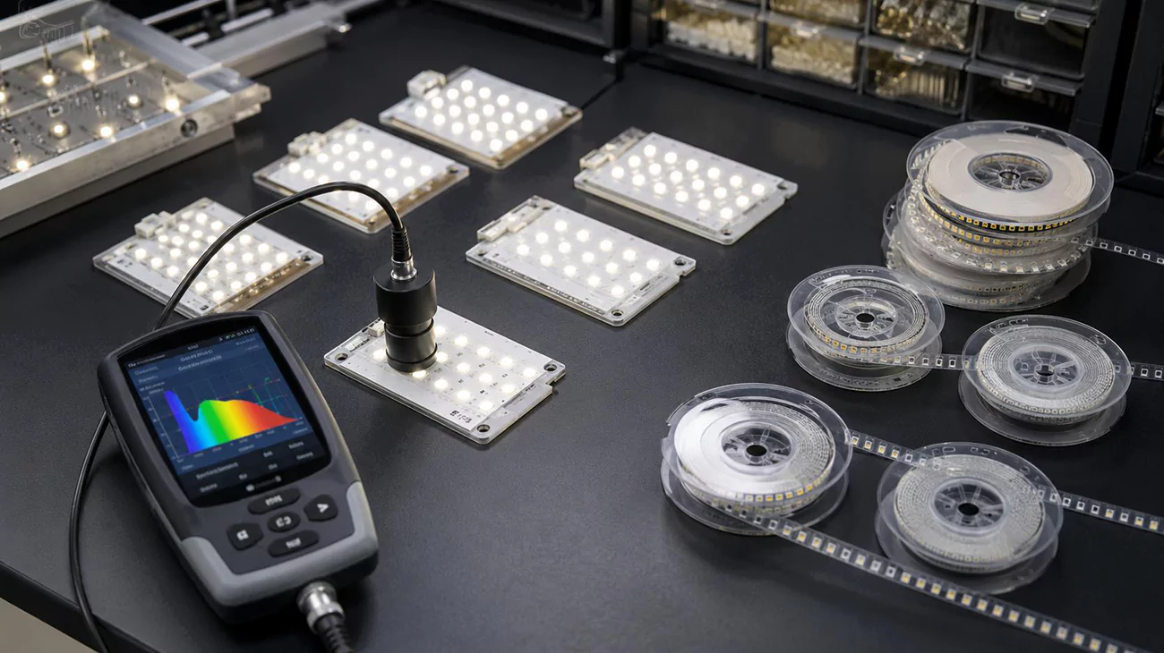
LED binning is the process of measuring LEDs and grouping them by defined characteristics such as color, luminous flux, or forward voltage. It reduces variation at the component input, but it does not by itself guarantee uniform color from a finished LED module or lighting fixture. Optical mixing, LED spacing, drive current, thermal conditions, calibration where applicable, and production-lot control still shape the result.
We prioritize a traceable bin specification: the measured range, test condition and reel identification must agree with the incoming-inspection record. That gives repeat orders a defined matching target. Send us the target CCT, chromaticity or wavelength, color tolerance, optical layout and operating conditions so our Higntek engineering team can develop the module around a traceable source specification.
What is LED Binning?
LED binning is the process of measuring and sorting LEDs into defined color, luminous-flux and forward-voltage ranges. Color bins define a region in chromaticity space for white LEDs or a wavelength interval for colored LEDs; flux bins define a lumen interval; and forward-voltage bins define a voltage interval at a stated current. Small differences in semiconductor growth, phosphor conversion and assembly during the manufacturing process produce variation even within one product family. Binning records that variation so the module designer can specify which groups are acceptable.
Color grading.
Color grading gives us a practical starting point for selecting the appearance of an LED module. For white-light specification, we use four broad CCT categories: warm, neutral, cool and extra cool. These categories help us translate the intended lighting effect into a source-selection range before narrowing the target color point.
| White-light category | CCT range |
|---|---|
| Warm white | 2700 K to 3500 K |
| Neutral white | 3500 K to 5000 K |
| Cool white | 5000 K to 7000 K |
| Extra-cool white | 7000 K to 10000 K |
We use the category to establish the design direction, then specify the exact target CCT within it. For a warmer appearance, we start with the warm-white range; for a more neutral or cooler appearance, we move to the corresponding range. A boundary value such as 3500 K is recorded as an exact target rather than left to the category label. This gives our LED selection and optical development a clearer brief than a request for warm or cool light alone.
Within the selected category, we prioritize chromaticity and the allowed color spread for modules that will be viewed together. A 3000 K and a 3500 K source both fall within the warm-white range, but that does not make them interchangeable for a matching installation. We recommend defining the target coordinates, SDCM tolerance and Duv limit where tint matters, then comparing the supplier’s bin regions with that requirement. Groups extending outside the accepted region need a narrower selection or additional screening. For colored LEDs, the equivalent selection uses the specified wavelength metric and its lower and upper limits.
Set the required CRI before source selection as well. Matching CCT or chromaticity does not establish how faithfully the source renders object colors, and CRI is a separate lighting requirement rather than a color-bin interval.
For adjacent modules and later replacements, we also recommend retaining the approved bin combination and comparing representative assemblies in the intended optics. Two sources can meet the same target-relative tolerance yet differ from each other. Carrying the color specification into the layout and prototype checks connects our source selection to the consistency the installation needs.
Luminous-flux grading.
Luminous-flux grading assigns measured lumen output to supplier-defined intervals at a declared current, temperature and optical test condition. A measurement method can make readings comparable under stated conditions, but it does not create universal component flux-bin thresholds; the interval belongs to the selected product and its stated test condition.
We select that interval from the module’s output budget, checking its lower limit against the required light output and its upper limit where channel or module balance matters. In the assumed 100 to 110 lm group used in the coding example, a 105 lm reading falls inside the interval while 98 lm and 112 lm fall outside it under the same test conditions. The supplier’s specification controls how readings on a shared boundary between adjacent groups are treated. A higher flux group earns its place when it meets the assembled output target within the power, thermal and optical budget, not because bin rank alone establishes efficacy or quality.
| Flux-grading element | What the grading defines | What the supplier must document | What we verify at module level |
|---|---|---|---|
| Measured property | Luminous flux in lumens at the declared drive current | The bin code and its lower and upper flux values | Assembled output against the module’s lumen budget |
| Test conditions | The current, temperature reference and optical condition at which the reading is valid | The declared current, temperature reference and optical test condition | That the comparison uses the same conditions as the module’s operating point |
| Boundary treatment | How a reading that falls on a shared boundary between adjacent groups is assigned | The product’s rule for boundary and permissible combinations | That the purchased grouping is unambiguous for the order |
| Traceability | Which production group the measured interval belongs to | Datasheet revision, bin code and lot or reel identity | Incoming inspection and later replacement matching |
Forward-voltage grading.
Forward-voltage grading assigns Vf readings to supplier-defined intervals at a declared current and temperature. No universal Vf-bin ladder applies across LED products; the selected interval is a product characteristic, not a quality score. We prioritize the full voltage range when selecting LEDs for a module, because the selected series count must work with the external driver’s operating range.
In the illustrative 3.0 to 3.2 V group, ten series-connected LEDs imply 30 to 32 V at the stated test point, before allowing for operating-temperature variation and other circuit requirements. That range gives a concrete basis for comparing source groups with the driver interface, rather than comparing nominal voltages alone. Parallel paths also need suitable current regulation; a narrow Vf group does not by itself establish balanced current sharing or higher quality.
| Vf-grading element | What the grading defines | What the supplier must document | What we verify at module level |
|---|---|---|---|
| Measured property | Forward voltage in volts at the declared drive current | The bin code and its lower and upper Vf values | Series-string voltage against the driver’s operating range |
| Test conditions | The current and temperature reference at which the reading is valid | The declared current and temperature reference | That headroom is checked across the full selected interval, not the nominal value |
| Boundary treatment | How a reading that falls on a shared boundary between adjacent groups is assigned | The product’s rule for boundary and permissible combinations | That parallel branches still receive suitable current regulation |
| Traceability | Which production group the measured interval belongs to | Datasheet revision, bin code and lot or reel identity | Incoming inspection and later replacement matching |
Hot binning
Temperature condition, or hot binning, identifies the thermal point at which color, flux and Vf are characterized. It is a measurement condition rather than a fourth universal grade. We recommend writing both the source test condition and the intended module verification condition into the specification. A room-temperature bin record provides one reference point; a module intended to run warm also needs its output and color evaluated after reaching its specified operating state. A source group is suitable when it supports the module’s acceptance limits at that working condition, not merely when its cold measurement looks favorable. Maximum rated temperature remains a separate limit. Hot binning changes the characterization point; it does not create a heat-resistance ranking or remove module thermal verification. After we complete the LED lighting module prototyping, we will also conduct thermal verification on the module.
| Temperature-grading element | What the grading defines | What the supplier must document | What we verify at module level |
|---|---|---|---|
| Measured property | Which of color, flux or Vf is characterized at the stated temperature | The property covered by the hot or standard record | Output and color at the module’s intended operating state |
| Reference point | The thermal point the reading is tied to | The stated junction, pad, case or specified reference temperature | That the module’s working condition is compared against the same reference |
| Test posture | Whether the record is standard-condition, hot-tested or hot-targeted | The declared posture of the test, not a temperature class | That the choice matches how the module will actually run |
| Separate limit | Maximum rated operating temperature, kept independent of the bin record | The rated maximum where the datasheet states one | That thermal design is verified separately from bin selection |
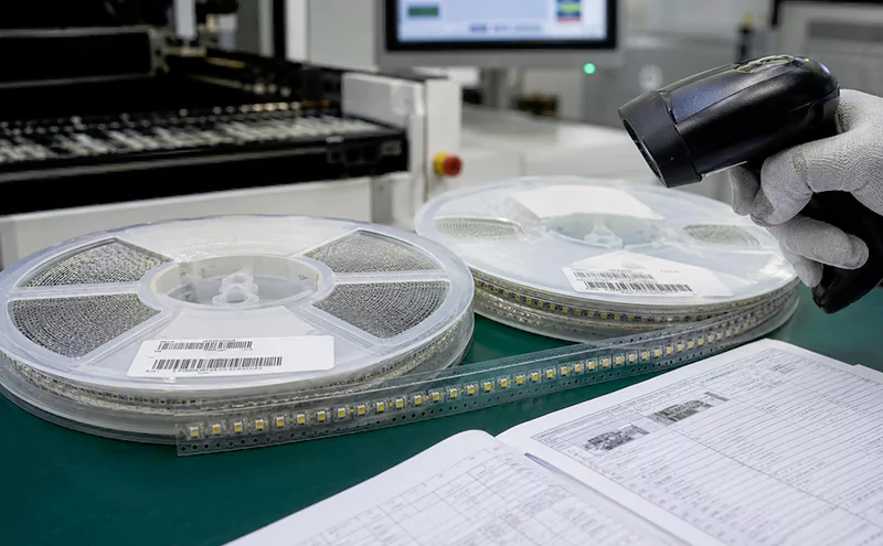
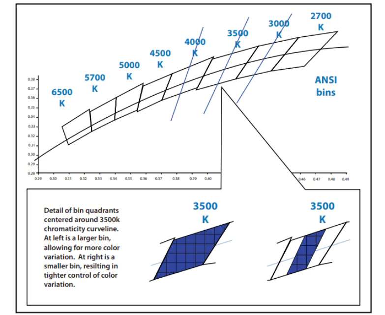
ANSI C78.377 specifies recommended chromaticity ranges for general lighting with solid-state lighting products, providing a common reference for communicating white-light color. Component selection still requires the LED manufacturer’s bin definitions. A bin code number structure can combine letters and numbers identifying flux, color and voltage groups; their order and meaning depend on the product’s code key. An LED binning chart maps those codes to measured ranges or chromaticity regions. Read the chart together with its test conditions and datasheet revision, then decode each field separately, as the example below illustrates.
The same LED has separate color, flux and voltage classifications because each describes a different measured property. For white LEDs, nominal CCT identifies the broad color target, while chromaticity-bin coordinates define the permitted region more precisely. A product model identifies the selected LED family and configuration; the reel bin code identifies the measured groups assigned to that shipment. During the module development process, we meticulously review all identification data and maintain records of LED component coding conventions and specification versions. This ensures that if any design changes are required, they can be verified against the original constraints and standards.
Information to identify | What it tells the project | What still needs verification |
|---|---|---|
Color bin | The allowed color region or wavelength group for the selected source | CCT, chromaticity coordinates or wavelength, Duv where relevant, and the target tolerance |
Flux bin | The component output group under the stated test condition | LED count, drive current, thermal condition, optics, and final module output |
Forward-voltage bin | The electrical range at the stated current and temperature | String architecture, driver range, current balance, and operating headroom |
Lot and reel identity | Which production group supplied the components | Replenishment matching, spare allocation, and incoming inspection records |
Example: Consider a fictional product, EXAMPLE-LED-A, with an illustrative reel code F2-C3-V1. Assume its code key defines F2 as 100 to 110 lm, C3 as a CCT band of 3950 to 4050 K, and V1 as 3.0 to 3.2 V, all at a test current of 350 mA and a junction temperature of 25°C. The reel code therefore identifies the permitted light-output, color-temperature and voltage ranges for this hypothetical shipment. Every code and value here is assumed for explanation. In an actual order, the supplier’s specification must also define the chromaticity region because a CCT band alone does not fully specify color matching. Use the supplied code key and test conditions to interpret the reel, then verify the assembled module at its intended operating point.
How Does LED Binning Affect Color Consistency in Lighting Fixtures?
White LEDs require a CCT target plus chromaticity coordinates and an accepted tolerance, while colored channels require a stated wavelength metric and interval. LED color binning narrows the source-color differences that a fixture must blend. For colored LEDs, violet, blue, green, yellow, orange and red occupy progressively longer parts of the visible spectrum; perceived color changes continuously across their boundaries.
Visible color | Approximate wavelength range |
|---|---|
Violet | 380 to 450 nm |
Blue | 450 to 495 nm |
Green | 495 to 570 nm |
Yellow | 570 to 590 nm |
Orange | 590 to 620 nm |
Red | 620 to 750 nm |
These broad color bands are not LED bin widths. A colored LED bin covers a much narrower product-specific interval, commonly expressed by dominant wavelength for perceived hue. White LEDs emit a combination of wavelengths, so their matching specification uses CCT and chromaticity rather than a single wavelength. Duv describes the tint offset from the blackbody locus, helping distinguish sources with similar CCT but different greenish or pinkish appearance.
Multi-LED mixing combines each source’s spectrum in proportions set by its output and the optical path. LEDs with different color points can produce a useful average when their light overlaps thoroughly. That average does not describe every position across the beam: individual sources can remain visible through a shallow diffuser or create colored fringes where their beams do not overlap. For RGB or tunable-white modules, channel-output differences also change the mixed color point.
Mixed-bin risk appears when the composition changes between boards, reels or replacement batches. Matching nominal CCT alone does not keep those mixtures identical. A replacement module can therefore look different from a neighboring module even though both carry the same CCT label. We recommend specifying the acceptable color region and replenishment-matching rule together, then retaining the bin and lot records for later comparison.
Array uniformity concerns the spatial distribution of color across a board, along a linear run and across the illuminated surface. Clustering LEDs from one edge of the permitted color region can create a local tint patch even when the module’s overall average meets its target. Distributing selected LEDs consistently and providing adequate optical overlap reduces this risk. Representative samples should be checked at the installed distance and angle, including board joints and beam edges.
How Does LED Binning Impact Lighting Design and Engineering?
LED binning affects optical-mixing requirements, drive-current matching, thermal-drift checks and LED layout strategy. It sets the initial color, output and voltage spread; the engineering task is to keep that spread within the finished module’s acceptance limits through the optics, circuit and thermal design.
- Optical-mixing requirements depend on the permitted color and flux variation. Wider source variation places more demand on mixing distance, lens behavior and diffuser scattering. A shallow optical cavity or direct view of individual LEDs leaves less room for blending. Tighter bins can reduce that demand, while stronger diffusion can improve blending at the cost of optical transmission. Bin selection and the available optical depth therefore belong in the same design decision.
- Drive-current matching connects the flux and voltage bins to the circuit. LEDs in one series string carry the same current, while their forward voltages add; the driver must sustain that string voltage across the intended operating range. Parallel paths without effective current regulation can share current unevenly when their Vf characteristics differ. That current imbalance changes light output and, in mixed-color systems, the balance between channels. Voltage sorting supports the design, but does not replace the required current regulation.
- Thermal drift changes the color and output measured at the factory test point. Junction temperature depends on drive power, the LED package, PCB construction and the heat path into the luminaire. Unequal temperatures across a board can produce unequal drift even among initially matched LEDs. Color and flux should therefore be checked after warm-up at the intended operating conditions, with thermal gradients considered alongside the original bin limits.
- Layout strategy determines which LEDs illuminate each part of the optical system. Closer spacing can improve overlap, but raises local power density unless LED power or board construction changes with it. A repeatable placement pattern should account for source color, output, optical alignment and heat distribution, rather than simply increasing LED count. The module layout must work within the available board dimensions and the lens or diffuser geometry.
We prioritize current, thermal state and optical-path checks when matched sources produce different finished results. Tightening the purchased bin will not correct a board hot spot or a poorly mixed beam. At the prototype stage, our module engineering brings LED selection, PCB layout and optical design together so those causes can be evaluated before production.
For a narrow visual tolerance, send us the target color, viewing distance, diffuser or lens constraints, board dimensions, drive current and thermal conditions. We will use those inputs to develop the LED layout and optical arrangement, then check the prototype against the intended application.
The Relationship Between LED Binning and MacAdam Ellipse And SDCM.
LED color binning selects source-color regions; MacAdam ellipses and SDCM describe how tightly those regions sit around a target in relation to human color discrimination. The ellipse supplies the local tolerance geometry, while SDCM, Standard Deviation of Color Matching, expresses its scale in steps.
Human sensitivity to a color difference depends on the starting color and the direction of the change. In a color-matching experiment, repeated matches scatter around the reference rather than landing at one exact point. MacAdam’s work represented that local variation with ellipses. It provides a basis for describing small color differences, rather than treating every equal coordinate distance as equally visible.
The CIE colorimetry framework describes color using defined observers, viewing conditions and coordinates. In the CIE 1931 xy chromaticity diagram, the curved outer boundary represents spectral colors, while mixtures occupy the interior and white-light targets lie near the central blackbody locus. The x and y coordinates identify chromaticity; they do not specify brightness. CCT follows the broad white-light target, while the position around it reveals finer tint differences.
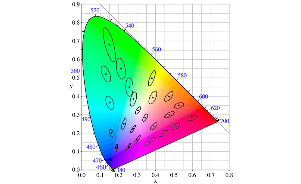
The regions are ellipses because discrimination is direction-dependent in this non-uniform coordinate space. At a given target, a coordinate change in one direction can be more noticeable than the same-sized change in another. The fitted region is consequently stretched, and its size and orientation change across the diagram. A single circular radius or a fixed Kelvin interval cannot reproduce that behavior everywhere.
- An n-step specification scales the local ellipse around the same target: a 2-step region has twice the one-step linear extent, a 3-step region three times and a 5-step region five times. A source inside the specified region meets that target-relative tolerance. The step number is neither a percentage difference nor a statement that every pair of LEDs inside the region has that same separation.
The useful application comparison is how much initial variation the visual task can tolerate. These are engineering starting points for sample evaluation, not mandatory application limits or guaranteed visibility thresholds.SDCM level
Relative color tolerance at the same target
Visual consideration
Application decision
1 step
Tightest region in this comparison
Very small target-relative differences; a perceptual reference, not an invisibility guarantee
Consider for demanding close comparison, reference matching or color-critical mockups when supply and measurement capability support it
2 steps
Twice the one-step linear extent
Tight matching, but sources near opposite edges can differ more than either differs from the center
Compare for adjacent wallwashing beams, continuous white surfaces or closely viewed architectural modules
3 steps
Three times the one-step linear extent
More permitted variation; appearance depends strongly on proximity, surface and optics
Evaluate for commercial, office and retail modules where the assembled sample demonstrates acceptable consistency
5 steps
Five times the one-step linear extent
Greater scope for visible tint differences, especially on adjacent neutral surfaces
Consider where sources are separated or thoroughly mixed and exact inter-fixture matching is less critical; verify the installation mockup
- A one-step ellipse is tied to statistical color-matching variation under particular observation conditions, not a universal boundary between visible and invisible differences. Viewing distance, adaptation, luminance, surrounding contrast and the illuminated surface all influence perception. A white wall receiving adjacent beams exposes a different matching task from a well-diffused source viewed in isolation.
At Higntek, we treat the supplier bin as a component input to the module specification. We compare its boundaries with the target ellipse, confirm whether the quoted SDCM applies to the LED, assembled module or complete fixture, and retain the actual color region for batch matching. A supplier bin may be a quadrilateral or another defined region rather than an ellipse, and sources on opposite sides of one target can both meet the tolerance while differing from each other.
During custom-module development, we check representative modules in the intended layout, optics and thermal conditions at the prototype stage. If the difference remains visible in that setup, narrower source selection and tighter batch matching have a clear purpose. If uneven temperature or incomplete mixing causes the mismatch, we correct the module design before tightening the purchased bin. This keeps the selected SDCM tied to a testable application requirement.
What Is the Difference Between LED Flux Bin, Color Bin, and Voltage Bin?
Flux bins control source light-output variation, color bins control chromaticity or wavelength variation, and voltage bins control the forward-voltage range at a stated current. They answer different design questions and must be specified separately; a close color match does not establish equal lumens, CRI or electrical behavior.
Flux Bin.
A flux bin affects the available lumen budget. At a common operating point, a lower-output group may require more LEDs or a different current to meet the module target, which changes power, heat and layout. The finished fixture then adds optical losses. Use the bin’s stated output interval when budgeting light, and validate module and fixture output at their own operating conditions rather than copying the component lumen value.
Color Bin.
A color bin affects the emitted hue and its consistency. For colored LEDs, wavelength binning constrains the hue of each channel; for white LEDs, chromaticity binning constrains the white point. Differences influence whether adjacent LEDs, modules and projected beams appear alike. They also change a multi-channel mixture, so the optical system and channel balance must be evaluated with the selected color groups.
Voltage Bin.
A voltage bin affects the electrical interface. Its Vf interval contributes to series-string voltage, driver operating headroom and the behavior of parallel branches. It also contributes to electrical input power at a given current. A designer must check the full selected interval and the temperature-dependent operating range; the nominal voltage printed beside a product name is insufficient for that check.
The comparison below connects each component classification to the evidence and assembled-module checks needed for a lighting design.
| Bin family | Primary control | Supplier evidence to request | Module-level verification |
|---|---|---|---|
| Flux bin | Component light-output grouping | Flux value or range, test current, temperature, and optical test condition | LED count, current, thermal state, optics, and final lumen target |
| Color bin | White-light chromaticity or colored-channel wavelength grouping | CCT and chromaticity or wavelength data, tolerance, Duv where relevant, and test condition | Mixed output, optical uniformity, visual target, and assembled-module color measurement |
| Forward-voltage bin | Electrical range at the selected operating point | Vf range, test current, temperature, and datasheet revision | String design, driver headroom, current distribution, and thermal operating point |
How Does LED Binning Affect Custom LED Module Design?
LED binning shapes a custom module’s source selection, color tolerance, lumen budget and electrical operating range. At Higntek, we develop the LED selection, PCB layout and optics around the application’s requirements. CCT, chromaticity coordinates, MacAdam tolerance, flux, CRI, voltage and efficacy each affect a different design decision; considering them together keeps a tighter component specification connected to a useful finished-module result.
- CCT gives custom-module development its first source-selection target. A brief that says only “warm white” still leaves the LED choice open. For a fixed-white module, the specification needs a defined target; for tunable white, it also needs the endpoint channels and the mixtures between them. We set those targets alongside the intended illuminated surface before choosing narrower bins. That gives LED selection and optical development a common reference, including the intermediate settings that endpoint specifications alone do not describe.
- Chromaticity coordinates turn that broad CCT choice into a matching requirement. For adjacent modules and phased installations, we prioritize a recorded target and accepted region, with Duv included when tint matters, so later material can be assessed against the same boundary. Retaining only the nominal CCT loses that control. We recommend carrying the approved source groups and replacement-matching rule into the module specification; this gives prototype evaluation and later purchasing a common color reference.
- MacAdam tolerance becomes a practical design choice when it is considered alongside the available mixing space. For adjacent beams on a neutral wall, we compare the accepted color spread with the LED spacing and diffuser distance before specifying tighter bins. If the layout leaves individual sources visibly separated, the mixing arrangement also needs attention. Higntek’s optical development combines LED selection and spacing with lens or diffuser adaptation, optical simulation and photometric testing. The prototype stage provides a way to assess the chosen tolerance in the intended layout and optics, where the customer will actually judge the light.
- Luminous flux creates a tradeoff between LED count, current and board space. When the output budget falls short, increasing current adds thermal demand; adding LEDs takes board area and changes the spacing available for optical mixing. We compare those options using the selected flux interval at the intended current and thermal condition, with optical losses included. At Higntek, LED selection, PCB layout and optical development are part of the same custom-module design process. Photometric testing then checks the prototype’s lumen output and distribution before mass production, helping establish whether the selected configuration meets the application’s output and dimensional requirements.
- CRI adds a color-rendering requirement that a close white-point match cannot supply. We recommend setting the required rendering performance before finalizing the source and power budget. When a project needs stronger color rendering, the selected spectrum can change efficacy and cost, so substituting a different LED affects more than the CRI entry on a specification sheet. Bringing that requirement into LED selection early lets the module’s LED count, current and thermal arrangement be developed around the source the application will actually use.
- Voltage binning helps determine the series count and external-driver interface. We prioritize checking the selected Vf interval over the intended current and temperature range before fixing the string layout. A circuit based only on typical Vf can leave insufficient operating margin at the ends of that range. For parallel paths, current-sharing requirements also influence the board design. We develop the module’s LED arrangement and PCB around the required electrical interface, so its specification gives the buyer a usable range for matching an external driver.
- Efficacy is the light output divided by electrical input power at a defined boundary. A higher flux group can improve that balance only when current, voltage, temperature and other conditions are compared consistently. Module efficacy includes the module’s electrical behavior; finished-luminaire efficacy also reflects driver and optical losses. We evaluate the source choice alongside the thermal and optical design rather than treating flux-bin rank as an efficacy rating.
LED binning is not simply a sorting process used to classify LEDs after production. For a lighting engineer, it is a practical way to control the variation that directly affects how an LED module looks, performs, and behaves in production. Flux bin influences luminous output, color bin affects chromaticity consistency, and voltage bin can influence electrical matching and driver design. For projects where multiple modules must look and perform consistently, these differences should be considered before the module design is finalized.
The relationship between LED binning, MacAdam ellipses, and SDCM is especially important when color consistency matters. A specified CCT alone does not guarantee that two LED modules will appear identical. The selected color bin and its SDCM tolerance define how tightly the LEDs are grouped around the target chromaticity. In applications such as continuous linear lighting, wall washing, retail displays, and architectural installations, a tighter bin can be worth the additional cost because even small color differences may become visible when modules are installed side by side.
From our experience developing custom LED modules, the most important point is that binning should not be treated as an isolated LED specification. At Higntek, we develop the module optical design alongside LED selection and PCB layout. We adjust LED spacing and lens or diffuser choices to the specified mixing distance and mechanical envelope, and use optical simulation and photometric testing to verify beam patterns, uniformity and lumen output before mass production. Our custom LED module development carries the design through prototype verification, inspection and manufacturing. For a binning-sensitive project, this provides a prototype stage at which to check the selected LEDs in their intended layout and optics before releasing the production configuration.
Production records carry the approved specification into repeat orders. Record the exact LED part number and datasheet revision, color target and tolerance, flux and Vf ranges, measurement conditions, bin code, production lot and reel identity. Include the assembled-module acceptance method and the matching rule for replacements or later project phases. Those records preserve the link between the prototype decision and incoming material.
Share the photometric requirements, dimensional constraints, color tolerance and operating conditions with us. We will develop a custom LED module prototype and use its optical and electrical checks to refine the design before production. We use this system-level approach when developing custom LED lighting modules. By controlling LED selection and bin requirements at the design stage, we can align the optical, electrical, thermal, and manufacturing requirements before moving into mass production. This helps customers achieve more predictable color consistency, output, and module-to-module performance instead of discovering binning-related problems after production has already started.
What Is the Relationship Between SDCM and MacAdam Ellipse?
A MacAdam ellipse describes a local color-matching region around a chromaticity target. SDCM expresses the scale of that region in steps. A smaller step count means a tighter target-relative tolerance, provided the same target and definition are used. It does not by itself specify brightness, CRI or the appearance of every pair of fixtures.
Is Lower SDCM Always Better for LED Lighting Quality?
Lower SDCM means tighter color matching, not automatically better overall lighting. It can justify extra cost for adjacent beams or color-critical surfaces, while wider tolerances may suit thoroughly mixed or separated sources. We recommend matching the tolerance to the visual task and sample results, alongside CRI, optics and operating conditions. At Higntek, we can tailor the LED selection and custom module design to your application, color tolerance and budget.
How Does LED Binning Affect LED Module Pricing?
Tighter bin requirements generally increase selection and inventory constraints, so demanding color consistency tends to cost more than a broader specification for an otherwise comparable module. Wider bins can improve purchasing flexibility. The actual premium depends on the LED, volume and available supply.
What Happens If Different LED Bins Are Mixed in One Project?
Uncontrolled mixing can create color or brightness differences across modules, replacements and project phases. Controlled mixing can work when the bin combination, layout and optics are designed and verified together. Retain bin and lot records, reserve matching spares where needed, and compare replacements with the installed lighting under the same operating conditions.
What Bin Information Should a Buyer Request?
Request the exact LED part number, bin family, bin code, measured value or range, test current, test temperature, optical condition where relevant, datasheet revision, production lot, and reel identity. For the module, also define the acceptance method for color, flux, electrical behavior, and assembled optical output.
Can LED Binning Alone Guarantee Fixture Color Consistency?
No. Binning reduces component variation, but fixture appearance also depends on spacing, optical mixing, drive current, driver conditions, thermal state, calibration where applicable, and batch control. Finished-module verification is needed when the application has a meaningful visual uniformity requirement.
Need Help Choosing the Right LED Bin?
Not sure which flux, color, voltage or SDCM specification fits your LED module project? Share your target CCT, CRI, output and application with our engineers for a practical recommendation.