-
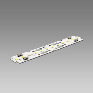
 HUL Series Linear LED Modules
72V 224lm/W High-Efficacy Linear Modules 20×560mm (1980lm)
-
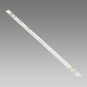
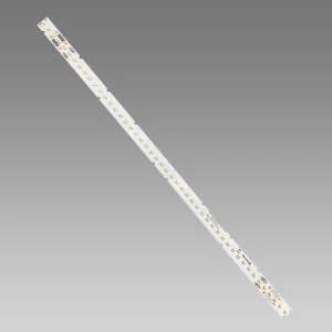
 HUL Series Linear LED Modules
72V 224lm/W High-Efficacy Linear Modules 20×280mm (990lm)
-
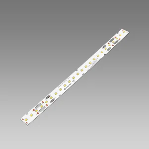
 HUL Series Linear LED Modules
225lm/W High-Efficacy Linear Modules 20×140mm (500lm)
-
 HUL Series Linear LED Modules
48V 224lm/W High-Efficacy Linear Modules 20×560mm (1980lm)
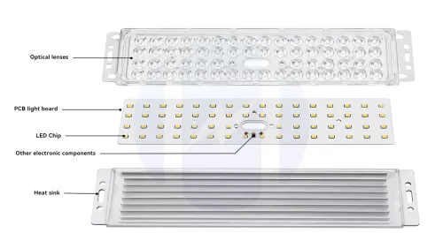
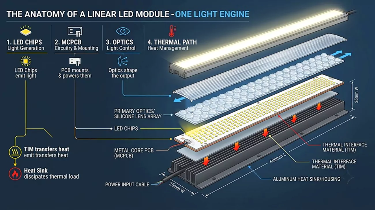
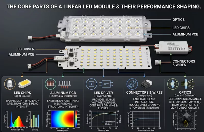
A linear LED module is built from six core parts: the LED chips that make the light, the PCB that carries and cools them, a driver that feeds them stable power, connectors that link the boards and the supply, optics that shape the beam, and the structural and thermal hardware that holds it all together. Each part decides a different slice of how the finished light performs, so the module is best read as one engineered system rather than a loose collection of parts.
LED Chip.
The LED chip is the light source of a linear LED module and the single biggest lever on its quality. Get the chip right and brightness, efficiency, and color all start from a solid base; get it wrong and no optics or thermal design can fully recover the result.
The model and brand of the chip matter most. Together they set the module’s brightness, luminous efficacy, color temperature, color rendering index (CRI), and rated lifespan — which is why two modules that look identical on a drawing can perform very differently once the chip is named. Higntek sources to each customer’s spec from the major international brands — Lumileds, Nichia, Cree, Samsung, Osram, Bridgelux, and Seoul — whose tight tolerances keep brightness and color stable from batch to batch. We also develops its own high-efficacy LEDs, built with a near-zero thermal-resistance package for cooler junctions and a silver-free, anti-sulfuration construction that resists the blackening which dims and shortens the life of ordinary chips in humid or corrosive air.
The LED chip determines the final effect. Larger chips can carry more current, and the volume of the light-emitting area also increases, directly increasing the maximum luminous flux that can be emitted. Forward voltage and drive current determine the series connection of the chips; the chip model determines the available colors and dimming options—depending on application requirements, different chips can be used for single-channel white light, adjustable white light, or multi-channel control, such as three-channel RGB.
| Package | Type | Typical use |
|---|---|---|
| SMD 2835 | Mid-power | High-efficacy linear runs, general and office lighting |
| SMD 3030 | Higher-power | High-flux output, high-bay and industrial fixtures |
| SMD 3535 | High-power | Outdoor, floodlight and spotlight fixtures at high drive currents |
| SMD 5050 | High-power, high-efficacy | Higntek’s flagship efficacy chip; also 3-in-1 RGB color |
| SMD 2020 | Compact mid-power | Tight pitch, slim profiles, signage |
| COB | Chip-on-board | Dense, spot-free uniform output |
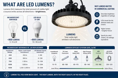
Higntek’s high-efficacy positioning centers on the 5050. At the top of the series, the chip reaches up to 280 lm/W under ideal drive conditions, about 265 lm/W once built into a module, and roughly 225lm/W in the finished fixture — well above the typical linear-module range.
PCB Substrate.
The PCB carries current to the LEDs and moves heat away from them, and 2 separate things decide how well it does that: the substrate material, and the fabrication process.
- Material comes first — what the board is actually made of. FR-4, a glass-fiber epoxy laminate, is the lowest-cost option used in LED lighting modules, but it conducts heat poorly and behaves more like an insulator, so it suits low-power decorative or backlight work rather than bright commercial runs. An aluminum (metal-core) substrate stacks a copper circuit layer, a thermal dielectric, and an aluminum base, so it doubles as a heat spreader and pulls heat straight off the LED junction — the mainstream choice for commercial led linear module designs. A copper base conducts heat roughly twice as well as aluminum, which earns it a place in high-power or high-density designs where the thermal load justifies the higher cost.
Material Thermal conductivity Max module power Relative cost Typical application FR-4 0.3–0.4 W/m·K ≤6W / Lowest Lowest Low-power decorative, indicator modules Aluminum (MCPCB) 1.0–3.0 W/m·K 6–50W Medium Standard commercial linear modules Copper 3.0–8.0 W/m·K 50W+ High Ultra-high-power, high-bay, thermal-critical OEM - Process is a separate axis — how the board is fabricated — and it shapes performance as much as the material. Every board, whatever its base material, carries a copper circuit layer for the current, and the weight of that layer is a process choice: standard strips often use 0.5oz (18μm) copper, while professional modules run 1–2oz (35–70μm), which lowers resistance, reduces self-heating, and carries higher current over a long run. Trace width and spacing serve the same purpose: reducing voltage drop and maintaining end-to-end uniformity. Adding thermal vias further improves heat transfer from the LED pads to the metal core or the back of the circuit board. Circuit board thickness and thermal conductivity determine rigidity and heat dissipation efficiency. Surface treatments (solder resist color for increased reflectivity and conformal coating for moisture protection) protect the circuit board and affect light output and field reliability.
From the moment a customer’s lighting-module requirements come in, Higntek selects the material — FR-4, aluminum, or copper — to the project’s lighting and electrical needs, then tunes the on-board process — trace width and spacing, copper weight, board thickness, and coating — for the best heat dissipation behind stable, long-life lighting.
LED driver.
A linear LED module can be powered three ways — constant-current drive, constant-voltage drive, or a driver built onto the board (DOB). Most professional modules use a constant-current driver, which holds output steady against small voltage swings and keeps brightness even down a long run. A DOB design instead integrates the power stage on the board as an AC linear LED module, dropping the external driver for a simpler, lower-cost install. Because drive method and dimming shape so much of how a module behaves, they get their own section below.
Connectors.
Connectors do two jobs — feed power into the module and link board to board — and a few types cover most needs: plug-in push terminals, solder joints, and power terminals, each trading assembly speed against permanence. End-to-end connectors let modules butt together into a seamless line with no dark gaps, and reputable terminal brands such as WAGO, Molex, and JST keep the contact reliable over years of service. Boards built to Zhaga interfaces use defined contact pads instead of soldered leads, so a certified module can be swapped or upgraded later without rewiring.
Optical Components.
Two optical parts shape the light once it leaves the chip: the lens and the diffuser. A lens controls the beam angle — narrow for accent work and wall-washing(10/15/30/60°), wide (up to around 160°) to cover more area without hotspots — while a diffuser spreads the output for soft, even illumination and lower glare. Good optical design is what lets a module hold a low UGR for offices and schools, and it is often the difference between a clean line of light and a row of visible hotspots.
Structural and Thermal Parts.
The remaining hardware is structural and thermal: heat sinks or aluminum profiles, a thermal interface material, wires, and a housing — included or left off depending on whether the module ships bare or as a finished light engine. A heat sink carries away heat the PCB cannot shed on its own, and a thermal interface material — adhesive, pad, or grease — bridges the PCB to that heat sink so the joint is not air-gapped. Wires connect the module to its driver, and fitting that assembly into the structural housing completes the finished luminaire.
Linear LED modules are the light engine inside four main luminaire families — surface-mounted, recessed, suspended, and backlit fixtures. The same board moves between them; what changes is the housing and how the light reaches the room. Picking the format is mostly a question of ceiling type, headroom, and whether the light line should be seen or hidden.
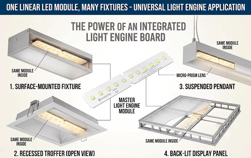
- Surface-mounted fixtures.
These attach directly to a finished ceiling or wall with no cut-out or grid access needed, which makes them the most common and most forgiving format. A linear led module runs the length of the channel behind a diffuser, and because nothing has to be recessed, the fixture drops onto drywall or concrete in minutes. That practicality is why surface-mounted runs dominate retrofits, office corridors, retail floors, and back-of-house areas — anywhere cutting the ceiling is not an option and a clean line of neutral white light is enough. - Recessed fixtures.
Here the fixture sits flush into the ceiling, wall, or floor so it does not protrude, either trimless for a seamless plaster-in look or flanged with visible trim. The module throws light down through a lens or diffuser while the hardware disappears into the structure. This is the minimalist choice for architectural interiors, conference rooms, and high-end retail, where lighting designers want the line of light but none of the visible fixture. - Suspended fixtures.
Hung from the ceiling on cables, suspended linear lights suit rooms with high headroom. Their advantage is bi-directional output: a module can light downward onto the work plane and upward to wash the ceiling, which cuts glare and adds depth to the space. Offices, hotels, bars, and restaurants use them to both illuminate and define a room, and because the format is modular, designers chain multiple modules into continuous lines of almost any length — the core idea behind modular linear led lighting. - Backlit fixtures.
In a backlit fixture the module hides behind a diffusing surface instead of facing the room. Backlit panels, illuminated signage, light boxes, and edge-lit displays all depend on even brightness across the whole face, so the module’s only job is uniform output with no visible hotspots. This is where optical design and tight LED spacing matter most — an advertising sign or a luminous ceiling looks premium or cheap based entirely on how evenly the light spreads.
Across all four formats the module does the same work. The lighting fixtures themselves determine how light is projected and how much hardware the human eye can see. This is where Higntek works less like a single supplier and more like an engineering-driven manufacturer: starting from the fixture type and application you are developing, it analyzes the core components from a lighting-module engineering view and, through material selection, design, prototyping, and testing, delivers a reliable module matched to the fixture you need.