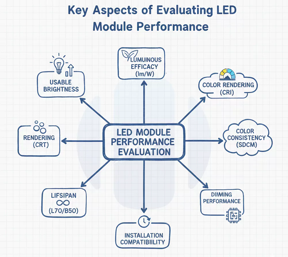
LED module performance should be evaluated by the results a customer can actually use, including the usable brightness, luminous efficacy, CRI, CCT, SDCM, lifespan, dimming behavior and installation compatibility. For a lighting OEM or fixture manufacturer, the first question is whether the LED module can meet the real lighting requirement and fit the final fixture before it moves into testing or production.
In many real projects, customers usually do not ask for “the best LED module” in a vague way. They will ask whether the module can reach the target lumen output after installation, whether the efficacy supports the energy target, whether CRI 90 is needed instead of CRI 80, whether 4000K modules still look consistent across batches, and whether dimming stays smooth with the selected driver. That is the right starting point for our performance evaluation.
| Performance point | Practical evaluation focus |
|---|---|
| Brightness | Whether the LED module delivers enough usable light after it is installed into the fixture |
| Luminous efficacy | Whether the module reaches a suitable lm/W range without creating unnecessary heat or power waste |
| CRI | Whether color rendering is good enough for the target scene, often CRI 80 for general lighting and CRI 90+ for higher color fidelity |
| CCT | Whether the white light tone matches the application, such as 2700K, 3000K, 3500K, 4000K or 5000K |
| SDCM | Whether multiple LED modules look consistent side by side or across batches |
| Lifespan | Whether brightness, color and electrical stability can hold up under real operating conditions |
| Dimming and control | Whether the module works smoothly with the intended driver or control method |
| Installation compatibility | Whether the module size, mounting, connector, lens height and diffuser distance fit the customer’s fixture |
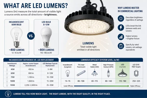
- Brightness is important, but when designing engineering projects, we ask our clients whether their lumen requirements are at the module level or the entire luminaire level. A LED module rated at 2000 lm does not mean the finished luminaire sends 2000 lm into the working area. Diffusers absorb light, lenses reshape the beam, housings raise the operating temperature, and some projects intentionally reduce drive current to keep heat and lumen depreciation under control. For a shelf light, cabinet light or linear office fixture, the better question is how much usable light remains after the LED module is assembled into the real product.
- Luminous efficacy needs the same careful reading. In many professional LED module projects, a practical module-level range often sits around 100-160 lm/W, while high-efficacy designs may move toward roughly 180-265 lm/W when the LED package, CRI target, CCT, drive current, thermal design and optics are well matched. I would not turn that into a blind race for the highest number. A module designed for CRI 90, warm CCT or smoother diffusion may naturally give up some lm/W, but that trade-off can be right when the application needs better color or visual comfort. The cleaner comparison is package-level efficacy, module-level efficacy and final fixture efficacy, not just one number pulled from a datasheet.
CRI, CCT and SDCM should be judged together because they decide how the light actually looks. For many indoor lighting applications, CRI 80 is a common baseline. For the retail, hospitality, beauty lighting, display lighting and other color-sensitive spaces, CRI 90 or higher is usually the safer target. For lighting applications with high color fidelity requirements, the latest TM-30 evaluation system can be used, which considers both Rf (color fidelity) and Rg (color saturation) to more comprehensively showcase the quality of the light source.
CCT should follow the scene. A 2700K or 3000K LED module gives a warmer feeling, 3500K to 4000K is often used in neutral commercial and office lighting, and 5000K or above is more common where clearer task visibility matters. A high-standard project does not choose these numbers by habit. It matches them to the product, space and user experience.
SDCM is easy to underestimate because one sample may look fine on the desk. The problem appears when many LED modules are installed side by side or delivered across batches. For example, two modules marked 4000K can still show a visible difference if color tolerance is loose. For visible linear lights, shelf lighting, panel lights and other continuous installations, for me, I would usually treat 3-step SDCM as the cleaner target when the budget and project level allow. A 5-step tolerance may work for many general applications, but long runs, premium retail areas and multi-batch projects often need tighter color control to avoid mixed-tone complaints.
Lifespan also needs correction. I would be careful with just a plain “50,000 hours” claim unless the supplier can explain the working conditions behind it. For an LED module, useful life is not only about whether the LEDs still turn on. It is about lumen maintenance, color stability, drive current, working temperature, solder joint quality, PCB heat transfer, driver matching and the final fixture structure. A module that still lights up but has lost too much brightness or shifted color beyond the project tolerance is not performing well from the customer’s point of view. All our LEDs undergo LM80 testing to maintain luminous flux, achieving a maximum of 5 years of L92B10.
Dimming and control should be checked before the project enters production. An LED module can look stable at full output and still behave poorly under 0-10V, DALI, PWM, Bluetooth wireless control or tunable-white operation. For commercial lighting, I would test the dimming range, low-end dimming stability, flicker behavior, startup response and color shift with the intended driver or control system. A module that works well at 100 percent output but flickers, steps or shifts color below 10 percent dimming can still cause complaints in offices, hotels, meeting rooms and high-end retail spaces.
Installation compatibility is the final filter. A good LED module should match the customer’s fixture structure before it moves into mass production. PCB length and width, mounting holes, connector direction, cable routing, lens height, diffuser distance and heat-sink contact area all matter. In one shelf-lighting project for a Malaysian retail fixture supplier we worked with, the first sample reached the lumen target and CRI requirement, but a connector near the optical window created a faint shadow line behind the diffuser. We revised the PCB layout, moved the wire path away from the light-emitting area and adjusted the diffuser distance by a few millimeters. The final sample looked more uniform without increasing LED power or adding extra heat load.
So, as a custom LED lighting module solutions manufacturer, Higntek’s value is not only producing LEDs modules after the design is fixed. Its engineering work covers LED matching, PCB layout support, optical and thermal design review, prototype verification, precision SMT assembly and controlled production. For customers comparing LED modules, that support helps turn high-standard performance requirements into a module that can actually work inside the final lighting product.
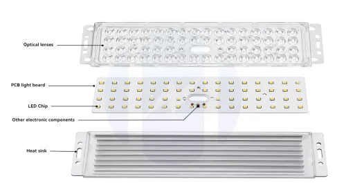
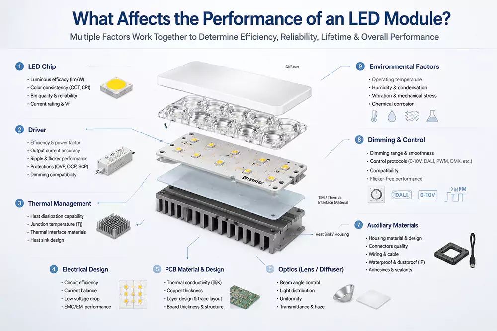
LED module performance is mainly affected by the LED chips, drivers, thermal management, electrical design, PCB material and layout, optical lenses, auxiliary materials such as diffuser plates, housings and wires, and dimming or control. These all parts work together as one lighting system, so I would not judge a module by chip brand or lumen output alone.
This is where many comparisons become too much simple. A better LED chip helps, but it cannot rescue a weak thermal path. A high-quality driver helps, but it cannot fix poor LED spacing or a bad diffuser distance. A metal-core PCB helps, but it still needs proper contact with the heat sink or housing. In custom LED modules, performance is not a single component advantage. It is the result of matched electrical, optical, thermal and mechanical design.
LED chips.
LED chips set the starting point. They influence luminous flux, luminous efficacy, CRI, CCT range, color binning and forward voltage. Still, I would not call the chip the whole product. The same LED package can behave differently on FR4, aluminum PCB or copper substrate. It can also show different stability when drive current, LED spacing and heat dissipation change. While manufacturers’ claims about LED parameters are helpful, ignoring other factors cannot guarantee that the LED chip will perform ideally in the final lighting module.
Drivers.
Drivers have a quieter role, yet they often decide whether the module feels stable in use. The LEDs need controlled current, so constant-current driving is common in many professional lighting modules. Driver selection affects flicker, dimming depth, startup behavior, electrical protection and current accuracy across LED strings. In long linear modules or tunable-white modules, the poor current balance can make one section brighter, warmer or less stable than another. That kind of defect is hard to correct after the PCB and housing are already fixed.
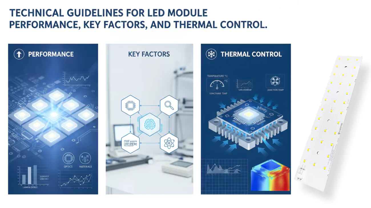
Thermal Management.
Thermal management is where optical and electrical performance either stay stable or begin to drift. Higher junction temperature can reduce light output, shift color behavior and shorten useful life. The practical heat path often runs from LED junction to solder pad, then to copper layer, PCB substrate, thermal interface, heat sink, housing and ambient air. The junction temperature depends on the drive current, thermal path and ambient temperature, which matches what we usually see in module-level engineering.
PCB.
PCB material and PCB layout deserve more attention than many buyers give them. For example, FR4 can work in lower-power or cost-sensitive modules, while aluminum PCB and other metal-core structures are often used when heat transfer matters more. Copper thickness, trace width, LED pitch, solder pad design, thermal vias, mounting holes and connector placement all affect the module. A clean PCB drawing is not only about manufacturability. It decides whether current flows evenly, heat leaves the LED efficiently, and the lens or diffuser can be installed without blocking the light.
Optical Control.
In LED lighting modules, optical lenses and diffusers determine the module’s luminous efficacy, uniformity, lifespan, and color rendering index (CRI). The transmittance of optical-grade materials in the lenses (such as optical silicone, PC, and PMMA) reduces light absorption and loss in the medium, thus improving the overall luminous efficacy of the module. Diffusers in linear lighting or multi-color mixing modules eliminate stray colors and multiple shadows, resulting in more uniform light mixing. Anti-yellowing performance determines the module’s long-term light decay. Refractive index and lens design control beam angle and glare, which are crucial for achieving precise light distribution.
Electrical design.
Electrical design is another place where small details become field problems. The number of LEDs in series, the number of parallel strings, resistor selection, driver IC choice, surge protection, polarity protection and wire gauge all shape reliability. I have seen low-cost modules fail not because the LEDs were poor, but because current distribution was not controlled well enough across parallel paths. Once temperature rises, a small electrical difference can turn into visible brightness difference. When we receive new project requests from clients, our engineers will focus on reviewing the entire PCB design and electrical design.
Auxiliary Materials.
Auxiliary materials are not secondary in the way the word sounds. Housings can protect the module and help installation, but they can trap heat when the internal air space is too tight. Wires and connectors look simple until they create shadow, voltage drop, loose contact or assembly interference. In LED modules for commercial fixtures, these small parts often decide whether the finished product feels refined or cheap.
Dimming and Control.
Dimming and control should be treated as part of the module design, not as a function added at the end. A module designed only for full-output operation may behave poorly under PWM, 0-10V, DALI, tunable white or Bluetooth wireless control. Low-end dimming often exposes weak driver matching first, through flicker, stepping, color shift or driver noise. For smart lighting projects, I would test the module with the intended driver and control system before mass production, because control problems are easier to correct while the circuit and BOM are still open.
A German office lighting OEM project we have can give a practical example. The customer needed a slim linear LED module for a suspended meeting-room fixture, with 4000K CCT, CRI 90 and smooth dimming below 10 percent output. The first sample reached the target lumen output, but after the opal diffuser and narrow aluminum housing were added, the center area ran warmer than expected and the low-end dimming showed slight stepping. The correction was not one dramatic change. We slightly reduced the drive current, upgraded the thermal conductivity material of the PCB aluminum substrate, adjusted the LED spacing near the center area, and modified the driver settings for smoother low-brightness dimming control. The final sample kept enough output, reduced visible hotspotting and behaved more steadily during dimming tests.