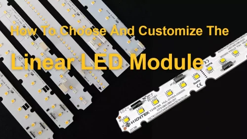
A good LED module is not the one with the biggest lumen number on the datasheet. I would judge it by how steadily it delivers light after the module is placed inside a real fixture, with heat, optics, driver current, PCB layout and installation space all working against each other.
This is where many LED module comparisons go wrong. A buyer may compare two LED modules by brightness and price first, then discover the real problem later when the light shows visible dots behind a diffuser, the color looks different across batches, or the module loses output faster in a narrow aluminum housing. The issue is not just one single component. LED chips set the basic light source, but the PCB material decides part of the heat path, the lens and diffuser shape the beam, the driver affects current stability and dimming behavior, and the assembly process decides whether the module can stay consistent in production.
For many professional lighting projects, I prefer to read LED module performance as an engineering result, not a marketing claim. Brightness, luminous efficacy, CRI, CCT, SDCM, lifespan, dimming control and installation compatibility all need to be checked together. That is also the right place to understand a manufacturer like Higntek. Its value is not only in producing LED modules, but in matching components, reviewing PCB and optical design, verifying samples, running controlled SMT assembly and keeping custom LED module production stable from prototype to batch delivery.
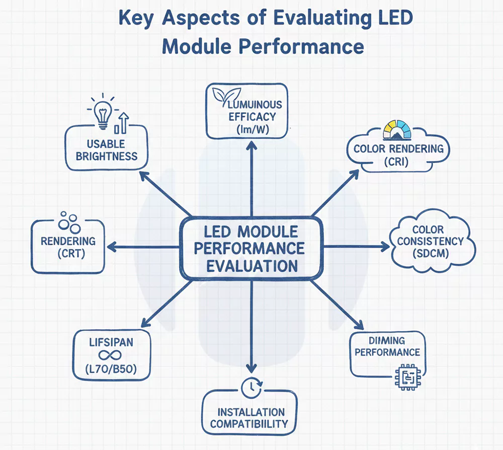
Key Aspects of Evaluating LED Module Performance.
LED module performance should be evaluated by the results a customer can actually use, including the usable brightness, luminous efficacy, CRI, CCT, SDCM, lifespan, dimming behavior and installation compatibility. For a lighting OEM or fixture manufacturer, the first question is whether the LED module can meet the real lighting requirement and fit the final fixture before it moves into testing or production.
In many real projects, customers usually do not ask for “the best LED module” in a vague way. They will ask whether the module can reach the target lumen output after installation, whether the efficacy supports the energy target, whether CRI 90 is needed instead of CRI 80, whether 4000K modules still look consistent across batches, and whether dimming stays smooth with the selected driver. That is the right starting point for our performance evaluation.
| Performance point | Practical evaluation focus |
|---|---|
| Brightness | Whether the LED module delivers enough usable light after it is installed into the fixture |
| Luminous efficacy | Whether the module reaches a suitable lm/W range without creating unnecessary heat or power waste |
| CRI | Whether color rendering is good enough for the target scene, often CRI 80 for general lighting and CRI 90+ for higher color fidelity |
| CCT | Whether the white light tone matches the application, such as 2700K, 3000K, 3500K, 4000K or 5000K |
| SDCM | Whether multiple LED modules look consistent side by side or across batches |
| Lifespan | Whether brightness, color and electrical stability can hold up under real operating conditions |
| Dimming and control | Whether the module works smoothly with the intended driver or control method |
| Installation compatibility | Whether the module size, mounting, connector, lens height and diffuser distance fit the customer’s fixture |
- Brightness is important, but when designing engineering projects, we ask our clients whether their lumen requirements are at the module level or the entire luminaire level. A LED module rated at 2000 lm does not mean the finished luminaire sends 2000 lm into the working area. Diffusers absorb light, lenses reshape the beam, housings raise the operating temperature, and some projects intentionally reduce drive current to keep heat and lumen depreciation under control. For a shelf light, cabinet light or linear office fixture, the better question is how much usable light remains after the LED module is assembled into the real product.
- Luminous efficacy needs the same careful reading. In many professional LED module projects, a practical module-level range often sits around 100-160 lm/W, while high-efficacy designs may move toward roughly 180-265 lm/W when the LED package, CRI target, CCT, drive current, thermal design and optics are well matched. I would not turn that into a blind race for the highest number. A module designed for CRI 90, warm CCT or smoother diffusion may naturally give up some lm/W, but that trade-off can be right when the application needs better color or visual comfort. The cleaner comparison is package-level efficacy, module-level efficacy and final fixture efficacy, not just one number pulled from a datasheet.
CRI, CCT and SDCM should be judged together because they decide how the light actually looks. For many indoor lighting applications, CRI 80 is a common baseline. For the retail, hospitality, beauty lighting, display lighting and other color-sensitive spaces, CRI 90 or higher is usually the safer target. For lighting applications with high color fidelity requirements, the latest TM-30 evaluation system can be used, which considers both Rf (color fidelity) and Rg (color saturation) to more comprehensively showcase the quality of the light source.
CCT should follow the scene. A 2700K or 3000K LED module gives a warmer feeling, 3500K to 4000K is often used in neutral commercial and office lighting, and 5000K or above is more common where clearer task visibility matters. A high-standard project does not choose these numbers by habit. It matches them to the product, space and user experience.
SDCM is easy to underestimate because one sample may look fine on the desk. The problem appears when many LED modules are installed side by side or delivered across batches. For example, two modules marked 4000K can still show a visible difference if color tolerance is loose. For visible linear lights, shelf lighting, panel lights and other continuous installations, for me, I would usually treat 3-step SDCM as the cleaner target when the budget and project level allow. A 5-step tolerance may work for many general applications, but long runs, premium retail areas and multi-batch projects often need tighter color control to avoid mixed-tone complaints.
Lifespan also needs correction. I would be careful with just a plain “50,000 hours” claim unless the supplier can explain the working conditions behind it. For an LED module, useful life is not only about whether the LEDs still turn on. It is about lumen maintenance, color stability, drive current, working temperature, solder joint quality, PCB heat transfer, driver matching and the final fixture structure. A module that still lights up but has lost too much brightness or shifted color beyond the project tolerance is not performing well from the customer’s point of view. All our LEDs undergo LM80 testing to maintain luminous flux, achieving a maximum of 5 years of L92B10.
Dimming and control should be checked before the project enters production. An LED module can look stable at full output and still behave poorly under 0-10V, DALI, PWM, Bluetooth wireless control or tunable-white operation. For commercial lighting, I would test the dimming range, low-end dimming stability, flicker behavior, startup response and color shift with the intended driver or control system. A module that works well at 100 percent output but flickers, steps or shifts color below 10 percent dimming can still cause complaints in offices, hotels, meeting rooms and high-end retail spaces.
Installation compatibility is the final filter. A good LED module should match the customer’s fixture structure before it moves into mass production. PCB length and width, mounting holes, connector direction, cable routing, lens height, diffuser distance and heat-sink contact area all matter. In one shelf-lighting project for a Malaysian retail fixture supplier we worked with, the first sample reached the lumen target and CRI requirement, but a connector near the optical window created a faint shadow line behind the diffuser. We revised the PCB layout, moved the wire path away from the light-emitting area and adjusted the diffuser distance by a few millimeters. The final sample looked more uniform without increasing LED power or adding extra heat load.
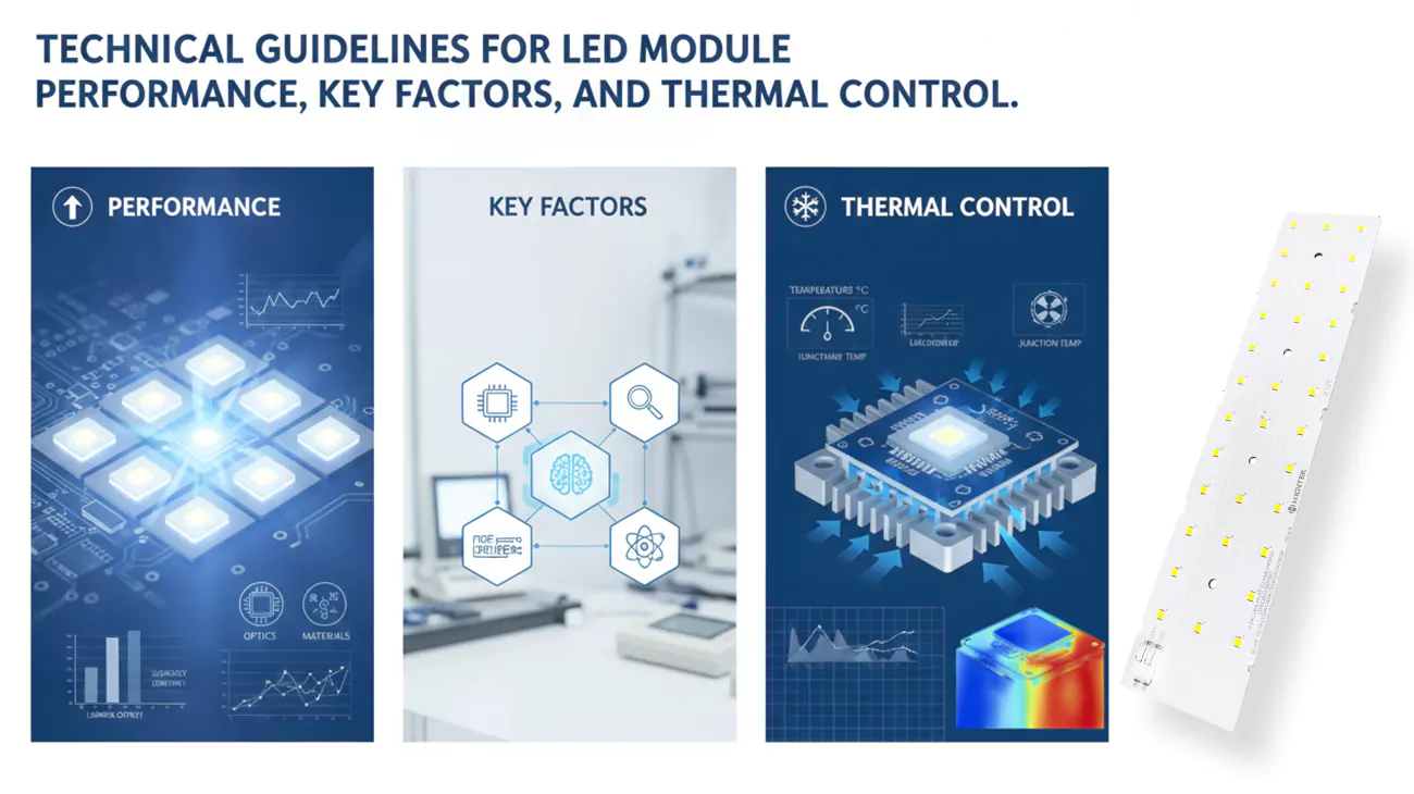
So, as a custom LED lighting module solutions manufacturer, Higntek’s value is not only producing LEDs modules after the design is fixed. Its engineering work covers LED matching, PCB layout support, optical and thermal design review, prototype verification, precision SMT assembly and controlled production. For customers comparing LED modules, that support helps turn high-standard performance requirements into a module that can actually work inside the final lighting product.
What Affects the Performance of an LED Module?
LED module performance is mainly affected by the LED chips, drivers, thermal management, electrical design, PCB material and layout, optical lenses, auxiliary materials such as diffuser plates, housings and wires, and dimming or control. These all parts work together as one lighting system, so I would not judge a module by chip brand or lumen output alone.
This is where many comparisons become too much simple. A better LED chip helps, but it cannot rescue a weak thermal path. A high-quality driver helps, but it cannot fix poor LED spacing or a bad diffuser distance. A metal-core PCB helps, but it still needs proper contact with the heat sink or housing. In custom LED modules, performance is not a single component advantage. It is the result of matched electrical, optical, thermal and mechanical design.
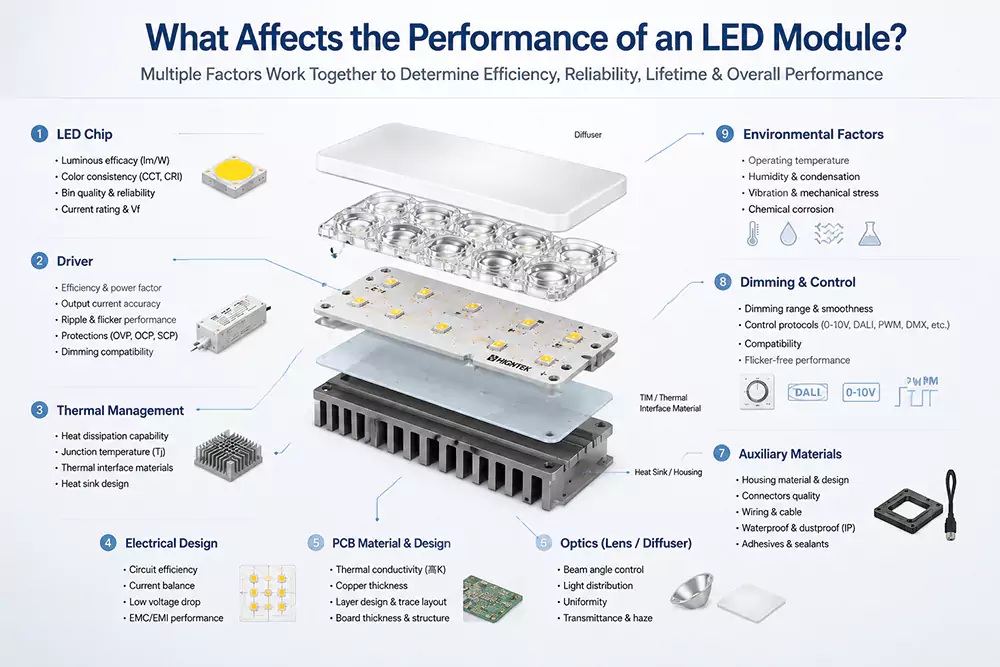
LED chips.
LED chips set the starting point. They influence luminous flux, luminous efficacy, CRI, CCT range, color binning and forward voltage. Still, I would not call the chip the whole product. The same LED package can behave differently on FR4, aluminum PCB or copper substrate. It can also show different stability when drive current, LED spacing and heat dissipation change. While manufacturers’ claims about LED parameters are helpful, ignoring other factors cannot guarantee that the LED chip will perform ideally in the final lighting module.
Drivers.
Drivers have a quieter role, yet they often decide whether the module feels stable in use. The LEDs need controlled current, so constant-current driving is common in many professional lighting modules. Driver selection affects flicker, dimming depth, startup behavior, electrical protection and current accuracy across LED strings. In long linear modules or tunable-white modules, the poor current balance can make one section brighter, warmer or less stable than another. That kind of defect is hard to correct after the PCB and housing are already fixed.
Thermal Management.
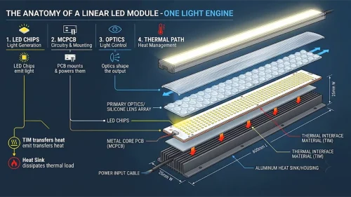
Thermal management is where optical and electrical performance either stay stable or begin to drift. Higher junction temperature can reduce light output, shift color behavior and shorten useful life. The practical heat path often runs from LED junction to solder pad, then to copper layer, PCB substrate, thermal interface, heat sink, housing and ambient air. The junction temperature depends on the drive current, thermal path and ambient temperature, which matches what we usually see in module-level engineering.
PCB.
PCB material and PCB layout deserve more attention than many buyers give them. For example, FR4 can work in lower-power or cost-sensitive modules, while aluminum PCB and other metal-core structures are often used when heat transfer matters more. Copper thickness, trace width, LED pitch, solder pad design, thermal vias, mounting holes and connector placement all affect the module. A clean PCB drawing is not only about manufacturability. It decides whether current flows evenly, heat leaves the LED efficiently, and the lens or diffuser can be installed without blocking the light.
Optical Control.
In LED lighting modules, optical lenses and diffusers determine the module’s luminous efficacy, uniformity, lifespan, and color rendering index (CRI). The transmittance of optical-grade materials in the lenses (such as optical silicone, PC, and PMMA) reduces light absorption and loss in the medium, thus improving the overall luminous efficacy of the module. Diffusers in linear lighting or multi-color mixing modules eliminate stray colors and multiple shadows, resulting in more uniform light mixing. Anti-yellowing performance determines the module’s long-term light decay. Refractive index and lens design control beam angle and glare, which are crucial for achieving precise light distribution.
Electrical design.
Electrical design is another place where small details become field problems. The number of LEDs in series, the number of parallel strings, resistor selection, driver IC choice, surge protection, polarity protection and wire gauge all shape reliability. I have seen low-cost modules fail not because the LEDs were poor, but because current distribution was not controlled well enough across parallel paths. Once temperature rises, a small electrical difference can turn into visible brightness difference. When we receive new project requests from clients, our engineers will focus on reviewing the entire PCB design and electrical design.
Auxiliary Materials.
Auxiliary materials are not secondary in the way the word sounds. Housings can protect the module and help installation, but they can trap heat when the internal air space is too tight. Wires and connectors look simple until they create shadow, voltage drop, loose contact or assembly interference. In LED modules for commercial fixtures, these small parts often decide whether the finished product feels refined or cheap.
Dimming and Control.
Dimming and control should be treated as part of the module design, not as a function added at the end. A module designed only for full-output operation may behave poorly under PWM, 0-10V, DALI, tunable white or Bluetooth wireless control. Low-end dimming often exposes weak driver matching first, through flicker, stepping, color shift or driver noise. For smart lighting projects, I would test the module with the intended driver and control system before mass production, because control problems are easier to correct while the circuit and BOM are still open.
A German office lighting OEM project we have can give a practical example. The customer needed a slim linear LED module for a suspended meeting-room fixture, with 4000K CCT, CRI 90 and smooth dimming below 10 percent output. The first sample reached the target lumen output, but after the opal diffuser and narrow aluminum housing were added, the center area ran warmer than expected and the low-end dimming showed slight stepping. The correction was not one dramatic change. We slightly reduced the drive current, upgraded the thermal conductivity material of the PCB aluminum substrate, adjusted the LED spacing near the center area, and modified the driver settings for smoother low-brightness dimming control. The final sample kept enough output, reduced visible hotspotting and behaved more steadily during dimming tests.
How Does Optical Design Affect Light Distribution?
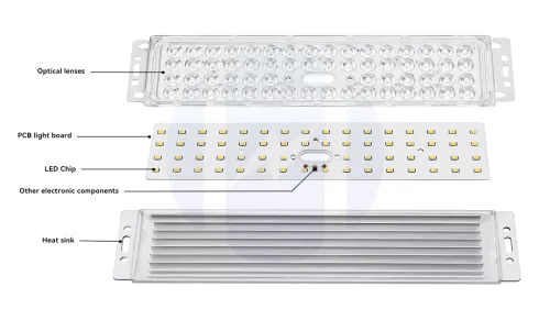
Optical design affects light distribution by controlling how light leaves the LED package, passes through lenses and diffuser plates, and reaches the final illuminated surface. I treat optics as a performance layer, not a cosmetic layer, because it directly changes uniformity, beam angle, glare, shadow, light loss and visual comfort.
LED.
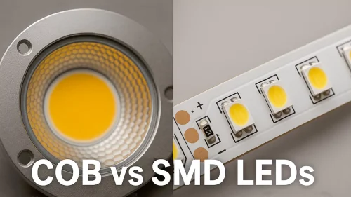
The LED package is the first optical decision. Different SMD packages, COB structures or high-power LEDs have different emitting surfaces, viewing angles and intensity distributions. A small, high-output LED can create stronger hotspots when the diffuser distance is short. A wider emitting surface may look smoother, but it may need more PCB space or different current planning. Optical design starts before the lens is selected. It starts with LED type, LED pitch and the distance between the LEDs and the optical cover.
Optical lens.
Lenses shape the beam angle and decide whether the LED module creates focused light, wide coverage or a softer mixed output. In many directional lighting designs, a 15°to 30°lens is used for a tighter spot, 45°to 60°works better for medium beam control, and 90°to 120°is often used when the module needs broader coverage. For diffused or backlighting modules, the beam can be much wider, sometimes reaching 120°to 175°depending on lens structure, diffuser design and LED spacing. But the angle itself is not the only answer. Lens material, surface texture, height, optical distance and mounting accuracy all affect whether the beam looks clean after assembly. When the lens sits slightly off-center, or when LED placement tolerance is not controlled well enough, the beam can become uneven even if the selected angle looks correct on paper.
This is why Higntek’s optical lens installation, LED PCB design review, component selection, sample verification and SMT assembly are relevant to real optical performance. The lens, PCB and assembly process have to match each other before the LED module can produce a stable light distribution inside the finished fixture.
Diffuser Plates.
Diffuser plates are usually where the customer first notices the result. A diffuser plate can hide LED dots, blend multiple LEDs into a smoother light surface and reduce harsh contrast, but it also absorbs part of the light. The balance depends on the diffuser material, haze level, thickness, LED spacing and optical distance. In a shallow fixture, a stronger diffuser may hide dots but reduce efficiency too much. In a deeper fixture, better spacing and lens selection may achieve uniformity without losing as much light.
A useful optical design does not chase uniformity blindly. It matches the application. Retail shelf lighting needs clean product visibility without strong dotting on glossy packaging. Office linear lighting needs comfortable uniform output and controlled glare. Outdoor modules may need wider beam coverage or specific distribution for wall packs and area lighting. Industrial task lighting may accept a stronger beam when visibility and durability matter more than softness.
In a retail freezer lighting module project we met for a Thai fixture supplier, the first sample reached the brightness target, but the acrylic cover showed two faint bright streaks near the center of the door frame. The issue came from tight LED spacing combined with a diffuser distance of less than 12 mm, which was too short for that SMD package and lens combination. We changed the LED pitch in the center zone, adjusted the lens angle, and increased the optical distance by 3 mm within the existing housing allowance. The final module was not simply brighter. It looked cleaner on the acrylic cover, and that was the real performance target for the application.
This is where custom LED module engineering has value. For Higntek, the relevant point is not just a broad sales claim. Its stated capabilities include LED chip and component sourcing, PCB layout support, optical lens and light distribution design support, thermal optimization, prototype verification and SMT production. Those are the exact links that decide whether an LED module has strong numbers on paper or a stable, clean lighting effect inside the final fixture.
How to Improve LED Heat Dissipation?
LED heat dissipation improves when we control heat at the source, shorten the heat-transfer path, choose the right thermal materials and let the fixture structure release heat into the surrounding air. I do not like treating heat dissipation as one extra heat sink added after the LED module is finished, because most thermal problems are already built into the design before the first sample is powered on.
The heat path is not complicated in theory. Heat starts at the LED junction, moves through the package and solder pad, spreads into the copper layer and PCB substrate, passes through the thermal interface material, then reaches the heat sink, housing and ambient air. The difficult part is keeping that path continuous. A small air gap, a weak PCB contact area, excessive drive current or a poorly matched housing can turn a good LED module design into a hot and unstable product.
- Material choice is the first lever. FR4 can work in lower-power or cost-sensitive LED modules, but compact high-output modules often need aluminum PCB, copper substrate or another thermally improved structure. The reason is not marketing. It is heat spreading. When heat stays concentrated around the LED pads, junction temperature rises faster, light output becomes less stable, and useful lifetime becomes harder to protect. High thermal conductivity materials help move that heat into a wider area before it reaches the housing.
- The heat sink and housing should be reviewed with the module, not after it. A thick aluminum profile does not automatically solve heat if the PCB only touches it at a few uneven points. Screw position, flatness, surface contact, air space and external airflow all matter. I have seen modules run hotter inside a visually “strong” housing because the internal contact was poor, while a simpler profile performed better because the PCB sat flat and heat could leave cleanly.
- Thermal interface material looks minor, but it often decides whether the real sample matches the design. Even flat metal surfaces have microscopic gaps, and air is a poor heat conductor. A thermal pad, grease or adhesive can reduce contact resistance between the LED PCB and the heat sink, but thickness and pressure need control. Too thick, and the material itself becomes a barrier. Too thin, and it may not fill the gap. This is one of those small details that rarely appears in a sales quotation but shows up quickly during aging tests.
- Electrical control (current and voltage) is an area that many buyers easily misunderstand. Current overload generates more heat, and higher junction temperatures reduce efficiency, alter color characteristics, and shorten lifespan. In fact, properly adjusting the drive, current, and voltage to match the desired light effect is more reliable for ensuring the stability of the luminaire than using overheated modules in pursuit of maximum lumen output. This is why we always ask customers about their current, voltage, and any special driver requirements when we receive a project.
- The heat-transfer path should be as short and clean as the structure allows. I would check the path from LED solder pad to copper area, PCB substrate, thermal pad, heat sink and housing. Every adhesive layer, air gap, plastic bracket or weak mechanical joint adds resistance. This is why PCB layout, copper area, solder pad design, screw holes and housing contact should be reviewed together. A heat sink cannot work well when the module cannot deliver heat to it.
- Driver design also belongs in heat dissipation. A driver does not only power the LED module. It controls current accuracy, ripple, dimming behavior and electrical stress. An inefficient driver or an aggressive current setting creates heat that the PCB and housing must absorb later. For dimmable or smart LED modules, driver matching becomes even more important because low-end dimming, PWM control or Bluetooth wireless control can expose instability that is not obvious at full output.
Achieving thermal management for LED lighting modules is not simply a matter of a massive heatsink or an expensive LED chip. It’s about striking a harmonious balance between materials, current, PCB layout, mechanical contacts, housing design, and driver selection. This is precisely where Hignetek excels, and you can find detailed explanations of our thermal management engineering approach here. As a manufacturer of custom LED lighting module solutions, Hignetek offers services including PCB layout design, FR4, aluminum and copper substrates, thermal simulation and optimization, driver matching, prototyping, SMT assembly, and controlled production. These capabilities are crucial because thermal performance must be designed, sampled, tested, and repeatedly validated in mass production, not just calculated on paper once.
Outlook for LED Module Development Trends.
LED module development is moving toward easier integration, smarter control, tighter thermal-optical coordination and more application-specific customization. I do not see the future LED module as just a brighter board with better LEDs. It is becoming a more complete lighting building block, where the electrical interface, optical structure, thermal path, control method and installation logic need to be considered together from the first design stage.
Plug-and-play design is one of the clearest changes. For lighting OEMs and fixture manufacturers, the real value is not only faster assembly. It also means fewer wiring errors, easier replacement, shorter production training time and more stable product platform planning. A plug-and-play LED module still needs serious engineering behind it. Connector type, polarity protection, driver matching, current setting, mechanical locking, thermal contact and cable routing all need to work together. Otherwise, “easy to install” can quickly become “easy to fail.”
Bluetooth wireless smart control is another trend already entering professional lighting. I would not simplify this into “every LED module needs Bluetooth.” That is not how most real projects work. The more practical direction is that LED modules need to be easier to pair with wireless drivers, control boards, sensors and tunable systems. A meeting-room luminaire may need smooth low-end dimming. A retail shelf module may need stable color across scenes. An office linear light may need daylight harvesting and occupancy logic. These functions depend on driver compatibility, LED circuit design, CCT channel balance, thermal stability and control testing, not only on adding a wireless label.
Thermal and optical integration will also become more precise. Higher-efficacy LEDs help, but compact luminaires, thin housings and stricter visual comfort expectations are making module design harder, not easier. A LED module needs enough light output, but it also needs controlled glare, smooth diffusion, stable color, acceptable surface temperature and reasonable cost. I expect more professional projects to use early optical review, thermal simulation, prototype aging and application-specific PCB layout instead of forcing one standard module into every fixture.
A strong LED module is never just a bright PCB with LEDs on it. The real performance comes from the way light output, efficacy, color quality, thermal design, optical control, driver matching and installation compatibility work together inside the final fixture. That is why I would always look beyond a single lumen value or a simple lifetime claim.
For lighting OEMs and fixture manufacturers, the better question is whether the LED module can stay stable in the real application. It needs to manage heat, keep color consistent, dim smoothly, fit the housing properly and remain repeatable in production. This is where custom LED module engineering becomes valuable. With support in component matching, PCB layout, optical and thermal design, prototype verification, SMT assembly and controlled production, Higntek helps turn LED module specifications into lighting products that can work reliably in practical projects.
In practice, LED module performance is never determined by a single factor. It is the result of a system-level balance between light source selection, electrical design, thermal control, optical engineering, and real installation conditions.
From our engineering experience at Higntek, many performance issues in real projects do not come from a “bad LED module,” but from mismatches between design assumptions and actual application environments. Small differences in PCB design, heat path structure, or driver selection can lead to noticeable changes in efficiency, stability, and lifetime.
This is why we always approach LED module development as a full engineering process rather than a component selection task. When all parameters are aligned properly, the result is not only higher performance on paper, but also more stable long-term lighting behavior in real-world installations.
For projects that require customized optical output, higher efficiency, or system-level optimization, working with an engineering-driven manufacturer can significantly reduce trial-and-error costs and improve final product reliability. At Higntek, we focus on helping clients turn lighting requirements into stable, manufacturable LED module solutions—from concept to mass production.
How does thermal management impact LED lifespan?
Poor heat dissipation makes an LED module age faster. It can still light up, but brightness may drop sooner, color may become less stable, and the whole module may become less reliable.
Heat does not only affect the LED chip. It also puts stress on the PCB, solder joints, driver parts and thermal materials. A good thermal design helps heat leave the module smoothly, so the LED module can keep its brightness and color performance for a longer time.
What is CRI and color temperature in LED modules?
CRI tells us whether colors look natural under the LED module. Color temperature tells us whether the white light looks warm, neutral or cool.
What causes LED module failure or degradation?
LED module failure is often caused by heat, driver or power supply problems, poor soldering, weak packaging, unsuitable materials or harsh working conditions.
In many cases, the LED chip is not the only issue. Unstable current, moisture, poor PCB heat transfer, damaged encapsulation or a housing that traps heat can all shorten module life. Reliable LED lighting modules depend on a complete design and manufacturing chain, from LED chips and PCBs to driver matching, thermal paths, and assembly quality.
What is a good luminous efficacy for LED modules?
For current LED lighting modules, 100-160 lm/W is a common practical range, achieving excellent energy savings without sacrificing color quality. Our newly developed ultra-high luminous efficacy design can reach approximately 190-265 lm/W.
Why do LED modules with the same CCT look different?
LED modules with the same CCT can still look different because color binning, SDCM tolerance, LED sourcing and batch control are not always the same.
Two modules marked 4000K may still show a slight warm, cool, green or pink difference when installed side by side. For visible linear lighting, shelf lighting or panel lights, tighter color consistency such as the 3-step SDCM is usually cleaner than looser tolerance, especially when many modules are used in one project.
Customize Your LED Module for Better Performance
Looking for higher efficiency, better heat control, or optimized optical design? Higntek provides OEM/ODM LED module development from PCB design to full assembly.