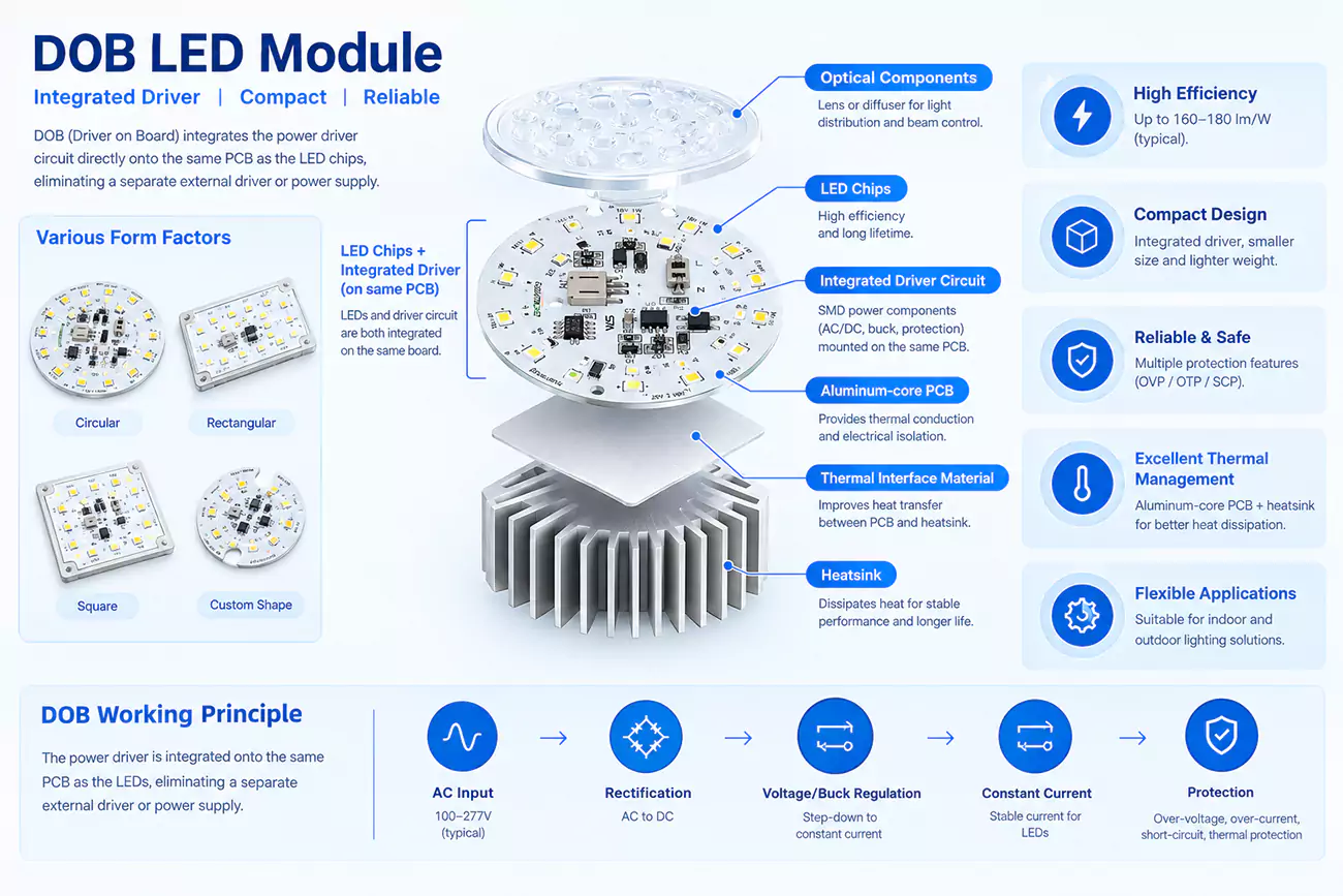
DOB technology, or Driver on Board, places the LED driver circuitry and LED array together on the same PCB rather than relying on a separate external driver. This integrated approach is widely used in compact DOB LED lights where board space, component layout and overall luminaire size matter.
DOB LED products are sometimes called driverless LEDs, but that description can cause confusion. The driver function is still there; it is simply integrated into the board. In practice, DOB is also not one fixed circuit design. Linear, switching, isolated and non-isolated architectures all exist, and each behaves differently once efficiency, power quality, safety and thermal performance become part of the design.
For lighting brands and engineers, that distinction matters. Two DOB LED modules may look similar on paper yet perform very differently inside the finished luminaire. What matters is how the DOB LED driver, LED array and board design work together to meet the project’s electrical, thermal and lifetime requirements.
What Is DOB Technology in LED Lighting?
DOB technology, or the Driver on Board, integrates the LED driver circuitry directly onto the same PCB as the LED array. Instead of treating the light source and power electronics as two separate assemblies, a DOB LED module brings them together at board level.
That compact structure is one of DOB’s most recognizable characteristics. Fewer connections between a separate driver and LED board can greatly simplify the internal layout of space-sensitive lamps and luminaires. But compactness is only part of the engineering story. Once the driver moves onto the board, electrical design, LED configuration, protection and thermal behavior become more closely linked. Changing the LED string, input voltage or driver scheme can affect the rest of the module rather than just one isolated component.
The word “driverless” can therefore be confusing. A DOB LED has not stopped needing a driver function. The rectification and current-control functions are still there; they are simply integrated onto the board. This distinction matters when evaluating a DOB LED light, because LEDs still need controlled current even when there is no external driver box.
There is another detail worth getting right from the beginning. DOB technology is an integration architecture, not one fixed power-conversion topology. Many AC DOB LED designs use non-isolated linear regulation, including high-voltage and segmented linear approaches. Switching DOB designs also exist, and isolation can be added where the electrical and safety requirements call for it. So DOB, linear and non-isolated should not be treated as the interchangeable terms.
This is useful when comparing two DOB boards that look nearly identical. The PCB dimensions and rated wattage may match, but their electrical behavior can differ because they use different LED-string voltages, current-regulation methods, isolation strategies or DOB LED driver ICs. For us, the DOB label is only the starting point. The circuit, LED load and PCB layout still have to be engineered around the finished lighting application.
Besides, the DOB’s clearest advantages come from compact integration, while its main limitations are engineering trade-offs created by bringing the LED array and driver electronics into the same board-level system.
| Advantages | Engineering Trade-offs |
|---|---|
| Compact module architecture | LEDs and driver electronics share a closer thermal environment |
| Fewer separate connections | Module-level servicing can be less independent |
| Simpler internal fixture layout | Surge, flicker and power quality depend on the onboard circuit design |
| Potentially fewer separate assemblies | PCB layout, protection and thermal design become more critical |
How Does DOB Technology Work in LED Modules?
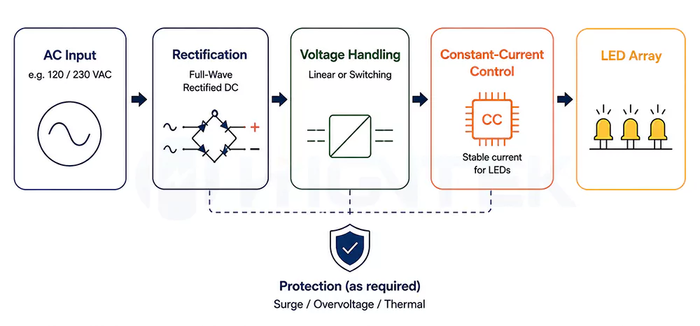
An AC DOB LED module generally follows five stages – the AC input, rectification, voltage handling, constant-current regulation and protection. The sequence sounds very simple, but one point causes a lot of confusion that not every DOB circuit “steps down” the mains voltage in the same way.
| Stage | What happens | What it means |
|---|---|---|
| AC input | Mains power enters the module PCB | The board must match the intended input-voltage range |
| Rectification | AC becomes full-wave rectified DC | Current is presented to the LED circuit with one polarity |
| Voltage handling | The circuit brings the available line voltage into a usable relationship with the LED load | Linear and switching DOB architectures handle this differently |
| Constant-current regulation | The DOB LED driver IC controls current through the LED array | Stable current keeps the LEDs within their intended operating range |
| Protection | The design deals with electrical or thermal abnormalities | Protection may address surges, overvoltage, excessive temperature or LED faults |
AC input and rectification come first. In an AC DOB LED, mains voltage reaches the board directly. A bridge rectifier then converts the alternating waveform into full-wave rectified DC. That does not mean the board suddenly has the smooth and low-voltage DC output we associate with a conventional low-voltage supply. Sequential linear LED driver reference designs, for instance, can operate directly from a 230 VAC line after rectification and control a long high-voltage LED string without a conventional magnetic conversion stage.
The voltage numbers make the reason easier for us to see. A 120 VAC sine wave has a peak of roughly 170 V, while 230 VAC reaches roughly 325 V. This is why many linear AC DOB designs work with relatively long series LED strings rather than treating the board like a 12 V or 24 V DOB LED strip.
The next stage is better described as voltage handling than just simply “step-down.” In a high-voltage linear DOB, the combined forward voltage of the LED string is designed around the rectified mains waveform, while the linear regulator controls the current and deals with the remaining voltage needed for regulation.
- Segmented linear DOB takes a more dynamic approach. The LED array is divided into taps or sections, and different sections conduct as the instantaneous rectified voltage rises and falls. Published sequential-linear designs use four or six LED taps and switch the regulators at different points in the AC cycle. This makes better use of the changing input waveform while keeping LED current controlled.
- A switching DOB handles voltage differently again. Instead of relying mainly on the relationship between the mains waveform and a high-voltage LED string, a switching stage actively transfers and converts energy. Non-isolated buck and buck-boost architectures are both established approaches in offline LED driving. One non-isolated buck reference design, for example, regulates 130 mA ±2.5% into a 15-21 LED load, and illustrating how a switching stage can create a controlled LED output from a much higher AC input.
Whichever DOB architecture we work with, one requirement does not change that the LEDs still need controlled current. LED forward voltage varies with device characteristics and operating temperature, so applying an uncontrolled voltage can push current beyond the intended operating point. The DOB LED driver IC or current-regulation circuit keeps the LED array around its target current as line and load conditions change. Offline LED driver technology is specifically designed around accurate constant-current output for this reason.
Protection closes the loop. Depending on the circuit and application, a DOB LED driver may include transient or surge protection, overvoltage and overcurrent protection, LED open/short protection, temperature sensing, thermal foldback or thermal shutdown. These are design choices rather than a checklist every DOB module automatically contains. Driver designs show both optional transient-protection components in simple sequential-linear circuits and integrated electrical or thermal protection in more sophisticated driver ICs.
In our DOB module development, we therefore look at the LED array, driver scheme and PCB layout together rather than treating the onboard driver as a last-minute addition. LED forward-voltage windows need to match the regulation range, PCB traces need to carry the rated current reliably, and the selected driver needs enough electrical and thermal margin for the intended fixture. That same integrated approach continues through prototype validation, SMT/PCBA production and testing in our custom LED module process.
What Are the Main Components of a DOB LED Module?
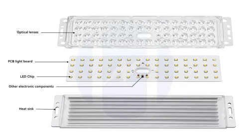
A DOB LED module is not defined by one special component. It is a board-level system that brings the PCB, LED source, LED array, rectification stage, current-control circuit, supporting protection parts, optics and mechanical structure into one module.
There is no fixed DOB BOM. A simple linear DOB circuit and a switching DOB circuit may use very different components even when the finished boards look similar. The useful question is whether each part matches the same electrical load, thermal condition and lighting application.
PCB Design and Substrate.
The PCB is the base of the DOB module. It carries the LED array and onboard driver circuit, sets the component layout and becomes part of the heat path inside the luminaire.
FR-4 can still be used in lower-power or cost-sensitive designs, but it is rarely the right choice when a DOB module has a meaningful thermal load. Once heat density rises, aluminum MCPCB or copper-based PCB structures usually give the module a stronger heat path. And the FR-4 is usually around 0.3-0.4 W/m·K, aluminum MCPCB about 1.0-3.0 W/m·K, and copper-based or higher-performance MCPCB solutions about 3.0-8.0 W/m·K.
Board thickness, copper thickness and thermal conductivity should be treated as separate decisions. Board thickness affects rigidity and fixture fit. Copper thickness affects current carrying, voltage drop and lateral heat spreading; common LED module copper weights may range from 0.5 oz to 2 oz, roughly 18 μm to 70 μm. Thermal conductivity describes how efficiently the substrate and dielectric structure move heat away from the LEDs and driver area.
This is where PCB engineering becomes more than choosing a material name. Copper distribution, trace width, dielectric quality, component spacing, thermal vias, surface treatment and board shape all affect whether the DOB module can carry current, control heat and fit the customer’s luminaire. A compact round ceiling-light module and a long linear module may need different combinations of board thickness, copper weight and thermal conductivity even when their rated power is similar.
LED Packages and Light-Source Selection.
In project discussions, people may call this part the LED chip. At module level, the more useful question is which LED package, series and electrical specification should be selected for the application.
Our current LED portfolio covers seven series, with package specification options including 2835, 3030, 3535 and 5050. The 2835 platform is commonly used for compact mid-power indoor applications such as tubes, panels and soft-strip style modules. The 3030 platform fits many outdoor and industrial lighting needs, including street, tunnel and industrial applications. The 3535 ceramic package is used where thermal performance is more demanding, such as high-bay, floodlight and stage applications. The 5050 platform covers high-power flagship and special lighting uses. LED size specifications serve only as an initial screening criterion; actual customization projects require selecting components based on specific application needs, voltage, current, and other factors. That range allows the LED source to be matched to different application needs instead of forcing one package type into every module.
For a DOB project, LED selection is not only about luminous efficacy. CCT, CRI, color consistency, forward voltage, operating current, power level and package thermal behavior all affect how the LED source works with the onboard driver. For example, indoor lighting may call for voltage options such as 3V-18V, while outdoor applications often work around 6V-24V options. Higher-power special applications may need a different electrical window again.
The goal is not simply to choose the brightest LED on paper. A high-efficacy source is valuable only when its voltage, current, thermal behavior and optical output fit the DOB circuit and the finished fixture.
LED Array and Driver Load.
The LED array is the way selected LEDs are connected and arranged on the PCB. In a DOB module, it is both the light-emitting surface and the electrical load controlled by the onboard driver.
For the driver circuit, the key factors are the total LED-string voltage and target current. Changing the LED count, series-parallel arrangement or tapped structure changes the load that the DOB driver has to regulate. This is why LED array design cannot be separated from driver matching.
Array layout also affects light uniformity and local heat concentration, but those details belong to the optical and thermal design stages. In this component section, the main point is simpler: the LED array must match the driver’s regulation range and the fixture’s required light output.
Bridge Rectifier.
The bridge rectifier is part of the AC input stage in many AC DOB modules. Its basic job is to turn the alternating polarity of AC input into full-wave rectified DC before the current-regulation circuit controls the LED load.
This part is often misunderstood. A bridge rectifier is not a complete LED driver. It does not regulate current, and it does not create the smooth low-voltage DC output associated with a conventional external power supply. It simply prepares the input waveform so the following DOB driver circuit can work with one current direction.
For module design, the rectifier still needs careful selection. Its voltage rating, current rating, package, losses and operating margin must fit the intended mains range and module power. Placement also matters because it sits near the input side of the circuit and can add its own heat load to a compact DOB board.
DOB LED Driver IC and Current Regulation.
The DOB LED driver IC is the main control device in many onboard-driver designs. Its job is to keep the LED array near the intended current as input voltage, LED forward voltage and temperature conditions change.
This is also where the “driverless LED” label can mislead buyers. The driver function has not disappeared; it has moved onto the LED board. In many linear DOB designs, the constant-current function is already built into the driver IC or current-regulation circuit, so a separate “constant-current chip” is not always another independent component.
The right driver solution depends on the architecture. A high-voltage linear DOB, segmented linear DOB and switching DOB may use different control methods and different supporting parts. A switching design may also require MOSFETs, inductors, diodes and additional capacitors, while a simpler linear design may use a smaller component set.
For Higntek, our value is not in manufacturing the driver IC itself. The driver IC is normally a sourced electronic component. The engineering value is in matching the driver solution to the LED array, designing the surrounding circuit and PCB layout, validating the prototype and controlling production consistency.
Why Do Some DOB Modules Run Hot?
DOB modules run hot when the LEDs and onboard driver create more heat than the PCB, thermal interface and housing can remove efficiently. High drive current, dense LED spacing, concentrated driver losses, poor PCB-to-housing contact and high ambient temperature can all raise local temperatures. The hottest point matters more than whether the whole board simply feels warm.
What Affects the Lifespan of a DOB LED Module?
DOB LED lifespan depends mainly on operating temperature, LED current, driver-component stress, surge exposure and the quality of the thermal and electrical design. Heat is especially important because both the LEDs and driver electronics age faster under excessive temperature. DOE notes that the good-quality LED lighting products commonly reach 30,000-50,000 hours or more, but also warns that electronic components can fail before the LEDs themselves, so LED-chip lifetime alone should not be treated as the lifetime of the complete module.
Not Sure If DOB Technology Fits Your LED Module?
Tell us about your LED module size, input voltage, power, dimming requirements, and application. Our engineers can help you evaluate whether a DOB architecture is suitable for your project.