24V LED Strip Voltage Drop: Formula, Wire Gauge Table and Maximum Run Length.

How do you calculate voltage drop in DC24V low-voltage LED strip lighting

The voltage you can afford to lose on a 24V strip is only about 1.2 V (5%), and two separate resistances compete for it: the feed cable and the strip’s own copper foil.

  • Budget: 5% of 24 V is 1.2 V. A 3 V loss is 12.5% on a 24 V system but only 1.4% on 220 V, so mains-voltage habits do not transfer.
  • Cable formula: ΔU = 2 × I × ρ × L / S. The “2” counts the out and return conductors. Forgetting it halves the answer.
  • Worked case: a 10 m, 14.4 W/m strip draws 6 A. On a 5 m RVV 2×1.5 mm² feed, the cable costs about 0.80 V. With a strip loop resistance of 0.025 Ω/m, the strip adds about 0.75 V. Total 1.55 V = 6.5%, already over budget.
  • Strip drop is I×R/2, not I×R, because current falls along an end-fed strip. It also grows with the square of the length, so halving the run cuts the strip’s own drop to a quarter.
  • Fix order that works: split or shorten the run, feed from the middle, then upsize the cable, then add a second power supply.

Why 24V punishes cable length: current, not voltage, sets the drop

For the same power, a 24 V circuit carries about 9 times the current of a 220 V circuit, and cable voltage drop grows with current, so the percentage loss on the same cable is about 84 times worse. That single ratio explains why installers with mains experience under-size low-voltage cable.

Voltage drop is Ohm’s law applied to the conductor:
ΔU = I × R, R = ρ × L / S
Here ρ is copper resistivity (0.0175 Ω·mm²/m at 20 °C, a rounded design value), L is the one-way cable length in metres and S is the cross-section in mm². Current flows out on one conductor and back on the other, so the loop length is 2L:
ΔU = 2 × I × ρ × L / S

The table shows the same 100 W load on the same 5 m, 1.5 mm² cable at two voltages.

System

Current

Cable drop (5 m, 1.5 mm²)

Drop as % of supply

220 V

0.45 A

0.05 V

0.02%

24 V

4.17 A

0.49 V

2.0%

The ratio is (220/24)² ≈ 84. This is also why ampacity is rarely your limit at 24 V: a 1.5 mm² copper conductor can typically carry roughly 15–20 A depending on installation method (approximate; check the ampacity tables in IEC 60364-5-52), yet voltage drop caps a 24 V strip system far below that.

What the standards say, and where they stop. IEC 60364-5-52 Table G.52.1 allows 3% for lighting circuits supplied directly from a public low-voltage network. The NEC’s non-mandatory informational notes recommend 3% on a branch circuit and 5% combined with the feeder; the same article states these recommendations are not NEC requirements. Both reference mains circuits. For a 24 V strip we use 5% (1.2 V) as a practical engineering target, not a code limit, for the reason below.

Why 5% is already visible on resistor-limited strips. Many 24 V strips put 7 white LEDs in series with a current-limiting resistor. Take 7 × 3.0 V = 21.0 V of LED forward voltage, leaving 3.0 V of headroom across the resistor at 24 V. If the segment sees only 22.8 V (a 1.2 V sag), headroom falls to 1.8 V and, to first order, LED current drops to about 60%. That is an illustrative first-order estimate; real strips vary, and constant-current strips hold brightness until the driver drops out. The point stands: a 5% voltage loss can mean a far larger brightness loss.

Worked example: a 10 m strip fed from one end

A worked example shows where the volts actually go. Take a 14.4 W/m strip (120 LEDs/m at 0.12 W each) running 10 m at 24 V, fed through 5 m of RVV 2×1.5 mm² cable.

Step 1: current. 14.4 W/m ÷ 24 V = 0.6 A/m, so 10 m draws 6 A.

Step 2: cable drop. With the loop formula:
ΔU = 2 × 6A × 0.0175 Ω·mm²/m × 5m / 1.5mm² = 0.7V
Counting one conductor only gives 0.35 V, half the true value. RVV cable is flexible (IEC 60228 class 5), whose maximum resistance at 20 °C is 13.3 Ω/km for 1.5 mm² rather than the 11.7 Ω/km implied by 0.0175. Using the class 5 figure, the cable drop is 2 × 5 m × 6 A × 0.0133 Ω/m = 0.80 V. Use 0.80 V as the design value.

Step 3: the strip’s own drop. The strip’s copper foil is a third resistance. If its end-to-end loop resistance (+ rail and − rail in series) is r = 0.025 Ω/m, then R = 0.25 Ω over 10 m. Current is not constant along the strip: it is 6 A at the feed and 0 A at the open end, so the average current through the foil is half. The strip’s drop is:
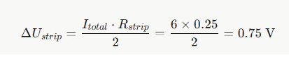
The formula for calculating the drop of a DC24V LED light strip

Multiplying the full current by the full resistance (1.5 V) overstates this by 2× for an evenly loaded, end-fed strip.

Item

10 m run (6 A)

20 m run (12 A)

Cable drop, ideal ρ = 0.0175

0.70 V

1.40 V

Cable drop, IEC 60228 class 5 (design value)

0.80 V

1.60 V

Strip drop, naive I × R

1.50 V

6.00 V

Strip drop, correct I × R / 2 (design value)

0.75 V

3.00 V

Total drop

1.55 V (6.5%)

4.60 V (19.2%)

Voltage at the far end

22.45 V

19.4 V

Decision. The 10 m run is slightly over the 5% (1.2 V) target; acceptable for decorative accent lighting, not for a cove where adjacent strips must match. The 20 m run is not a design: its far end sits at 19.4 V. Both numbers assume r = 0.025 Ω/m, and the next section shows why you should not assume that value.
FAQ

How long can a 24V LED strip run before it dims?

It depends on two limits, and the shorter one wins. For a 14.4 W/m strip on 1.5 mm² cable, the cable alone allows about 9 m (Table 1). The strip’s own copper, fed from one end, allows about 12.6 m at 0.025 Ω/m but only 4–6 m at 0.10–0.25 Ω/m (Table 2). Without a measured loop resistance, stay at or below the Table 2 length for single-end feed, and centre-feed to go up to about twice that.

Current travels out on one conductor and back on the other, so the resistive path is twice the one-way cable length. The correct loop formula is ΔU = 2 × I × ρ × L / S. Using one conductor only reports half the real drop, which is the most common low-voltage calculation error.

Start Your Custom LED strip Module Project

Tell us your luminaire dimensions, driver information, and lighting goals—our engineering team can help you develop the right LED strips solution faster.

On-Time Delivery 99.38%

Consistent production & reliable global delivery

End-to-End Engineering Support

From design optimization to production guidance

3-Day Rapid Prototyping

Fast sampling to accelerate product validation

100% Quality Inspection

Full testing ensures stable and reliable performance

Higntek-icon logo

Discuss LED module project specifications with professional engineers.

Pre-Engineering Inquiry