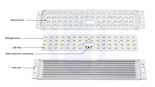
Choose an LED channel by matching the complete populated LED module to the installation, then checking heat transfer and the finished light output. PCB width is the starting dimension. Connectors, fixing screws, cover retention and the space above the LEDs determine whether the assembly can be built, cooled and serviced. A channel selected around the bare board can create expensive late changes: a connector may obstruct the diffuser, a recessed mounting may restrict cooling, or a shallow cavity may leave visible LED dots. The useful specification joins the mechanical drawing, operating power and optical target before the profile is ordered. For custom High-efficiency LED lighting modules, if a customer provides existing channel drawings and specific application requirements, Higntek engineers will develop the LED board—along with its electrical, thermal, and optical interfaces—based on the customer’s intended component structure.
What Is an LED Channel?
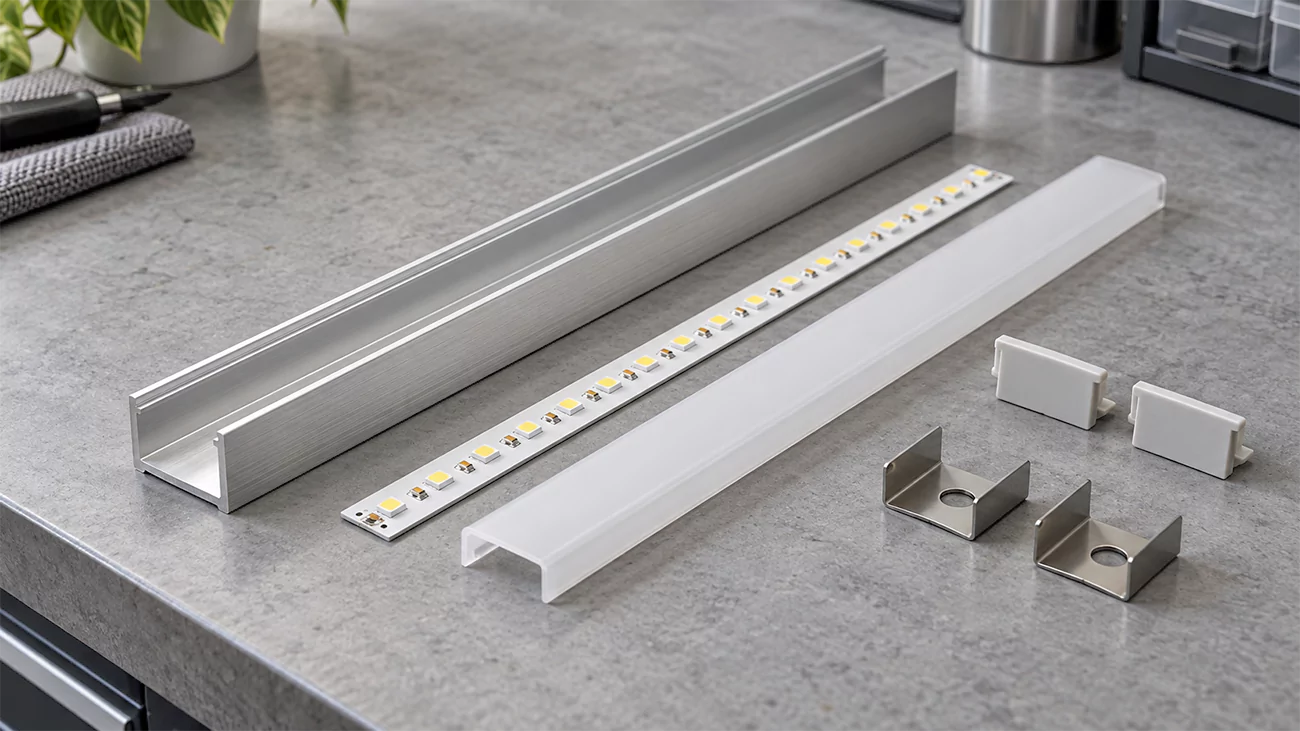
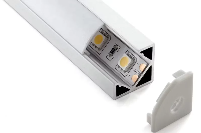
An LED channel is a housing that locates and supports an LED light source, commonly with a removable diffuser. It is also called an LED profile, an LED extrusions or an LED light channel, and it often uses an aluminum extrusion as its structural body. The extrusion is the shaped metal section; a channel kit may add a cover, end caps and mounting hardware. Over a long run, the same section serves as a linear lighting housing that carries the light source and its cover as one continuous assembly.
Heat spreading is one of its main functions. When the LED board has a suitable thermal connection to the aluminum base, heat can spread into the profile and pass to the surroundings. A board suspended above the base or attached through a poor interface cannot use the metal as effectively.
Physical protection comes from the body and cover surrounding the light source. They help shield the board from handling and incidental contact. Environmental protection depends on the completed construction, including joints and cable entries.
Optical control comes from the diffuser, its distance from the LEDs and the shape of the cavity. These features affect visible dots, the direction of light and the appearance of the illuminated line.
Installation reliability comes from defined fixing surfaces, compatible clips and accessible connections. The LED mounting channel establishes where the board sits and how the assembly attaches to the furniture, wall or ceiling. Our review of customer drawings puts most late changes at this assembly boundary rather than in the profile itself, so the parts list and its interfaces are what we check first.
What are the main components of an LED channel?
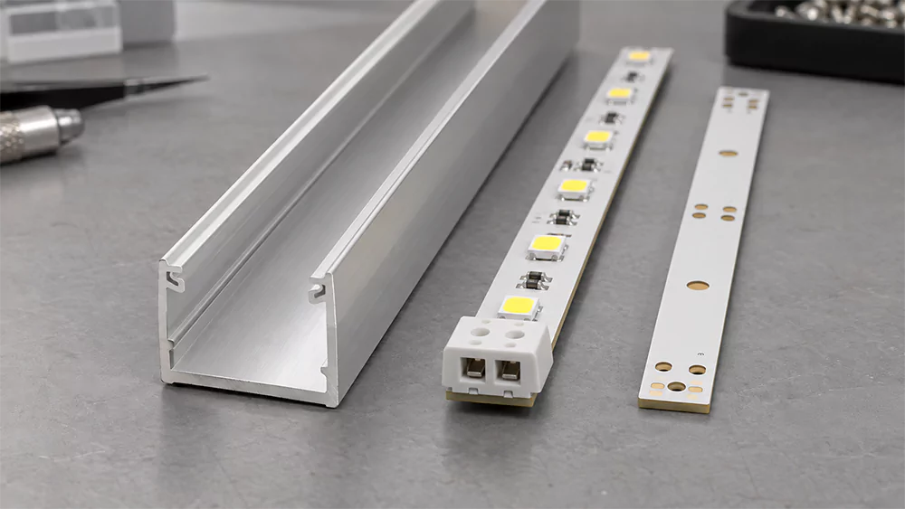
The main components are the profile body, diffuser cover, mounting accessories and end caps. The LED source and electrical components may be supplied separately, so the bill of materials should identify every included part, and a quotation should state whether it covers a bare LED aluminum channel, a hardware kit or a powered assembly.
The aluminum profile provides the base, sidewalls and cover-retention features. Its usable cavity determines component clearance, while the base and exposed surfaces contribute to heat transfer. External width alone does not describe either function.
The diffuser cover closes the light aperture and modifies the visible output. Clear, frosted and opal materials offer different balances of transmission and scattering; shaped lenses can control the beam. The cover must match the profile retention geometry.
The mounting accessories secure the channel to its support. Clips, brackets or suspension hardware must suit the installation and load. Separate screws, retainers or an appropriate adhesive system fix the PCB to the channel base.
The end caps finish the ends and may accommodate cable exits. Their thickness, fastening and removal method affect usable length and service access. A cap that fits the profile does not by itself establish a waterproof assembly.
Selection point
Rigid LED module
Flexible LED strip
Geometry
Fixed board shape and component envelope
Bends within its specified limits; suits compatible curved routes
Length adjustment
Requires a specified cuttable design or a board made to length
Cutting follows the designated electrical cut points
Fixing
Screws, retainers or a suitable bonding system
Often an adhesive backing, with retention matched to service conditions
Interfaces
Connector height and tool access can drive cavity size
Solder joints, feed wires and strip connectors still need clearance
Optics and power
Layout, drive current and secondary optics can be customized
LED pitch, current and strip construction vary by product
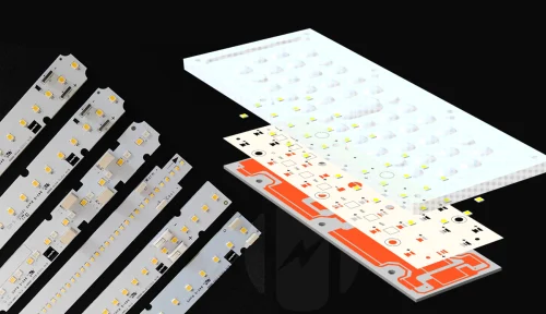
The light source may be a rigid LED module or a flexible strip. A rigid board offers a stable platform for selected LED layouts, connectors and optics; a flexible strip accommodates permitted bends and modular cut lengths. Rigid, high-efficiency LED modules are ideal for custom lighting applications with specific power and thermal management requirements, while standard flexible LED strips help streamline routine installation processes. These are common design differences. The selection depends on the actual product design.
What Are The Different Types of LED Channels?
LED channels are commonly grouped by mounting method: surface mounted, recessed, suspended or angled. Round describes the section shape and can occur within several mounting families. Choose the installation interface first, then confirm the internal cavity. Our selection judgment is to preserve the module space and service route while choosing the visible form. A visually compact profile loses its benefit if the board or diffuser cannot be removed after installation, and our experience is that the limit comes from a different part of the installation in each family.
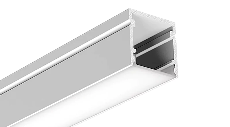
Surface mounted LED channels. A surface mounted channel fixes to a finished surface, which suits cabinets, shelving and retrofit runs where no cavity can be cut. Clip engagement, the visible cable route and the condition of the mounting surface then decide how straight and serviceable the run stays.Surface mounted LED channels
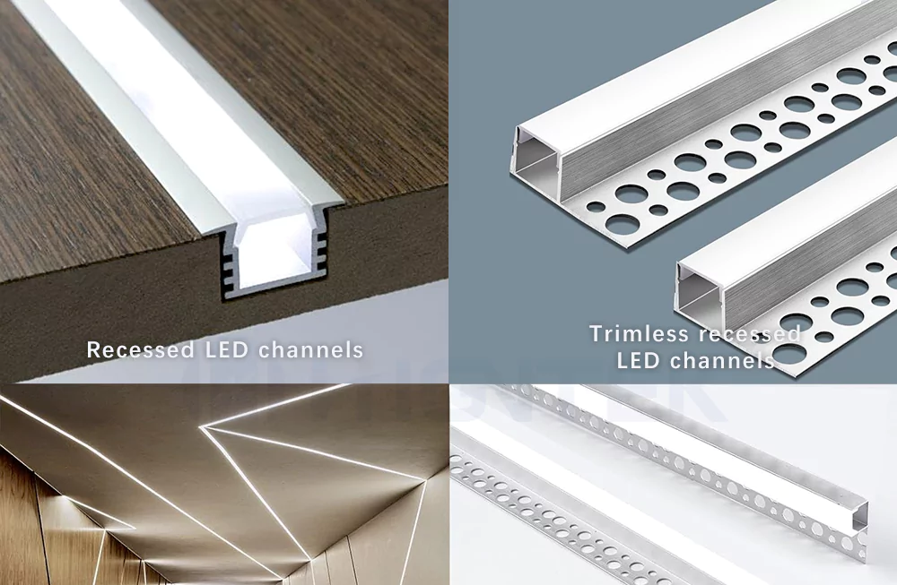
Recessed LED channels. A recessed channel sits in a prepared slot so the light line reads as part of the surface, which is why it dominates furniture and architectural details. That integration costs installation tolerance: the cutout, the flange coverage, the cavity depth and the cover removal route all have to be coordinated, and a confined slot cools differently from a profile measured in free air.Recessed LED channels and Trimless recessed LED channelsTrimless recessed LED channels. A trimless channel goes further and leaves only the aperture visible, with no flange across the finished surface. The building sequence then becomes part of the specification, because the finish, the alignment along the run and any later access to the board or cover must be settled before the surrounding surface is closed.
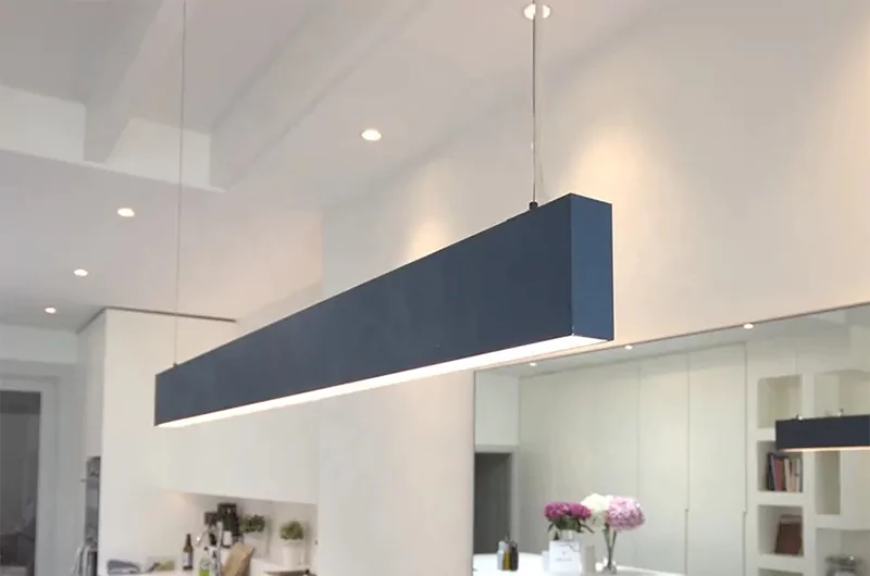
Suspended LED channels. A suspended channel hangs as a pendant or as a continuous suspended run. Suspension hardware, balance, joint alignment and the power entry have to be specified together, since the profile no longer rests on a continuous support.Suspended LED channels
Corner or angled LED channels. An angled channel turns the aperture toward a work surface or away from a normal sightline. The section angle alone does not set the beam, so the profile orientation and the optic are matched to the surface that has to be lit.Corner or angled LED channels
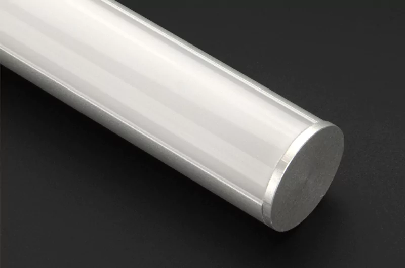
Round LED channels. A round channel gives the fixture a cylindrical or curved exterior where the profile itself is visible. The internal board seat and the matching cover still need checking, because a round section is not automatically bendable.Round LED channels
Channel Type
Characteristics and Typical Application
Selection Constraint
Surface mounted profile
Attaches to a finished surface; useful for cabinets, shelving and retrofit linear lighting
Check clip engagement, visible cable routing and the mounting surface
Recessed profile
Fits a prepared slot for an integrated light line; used in furniture and architectural surfaces
Integrates with the surrounding finish for a minimal visible edge
Coordinate finishing sequence, alignment and later access before the surface is closed
Suspended profile
Forms a pendant or continuous suspended run
Specify load-bearing suspension, balance, joints and power entry together
Corner or angled profile
Directs the aperture toward a work surface or away from a normal sightline
Match the profile orientation and optic to the target surface; section angle alone does not define the beam
Round profile
Provides a cylindrical or curved exterior for visible linear fixtures
Check the internal board seat and compatible cover; a round section is not necessarily bendable
These categories overlap. A curved route needs a profile and light source designed for bending, whereas a round suspended housing may contain a straight rigid board. A channel for LED strip and a channel for LED tape describe the light source rather than the mounting family, so both still have to be checked against the tape fixing method, bend radius and designated cut points.
How to Choose the Right LED Channel for an LED Module?
Match five connected factors: the populated module dimensions, electrical power per length, mounting method, thermal requirements and optical requirements. Resolve fit first, then verify the powered assembly in the intended installation. A change to one factor can force another: a deeper profile may improve mixing space but conflict with the recess depth.
Choose the Right LED Channel for an LED Module
LED lighting Module Dimensions.
Module dimensions include every fitted component. Check PCB width and length against usable internal dimensions at the height where the board will sit. Then check connectors, solder joints, screw heads, wire bends and any lenses against the cavity at their own heights. Diffuser locking lips can narrow an otherwise generous opening. Drawings should also define board tolerances, hole positions, end-cap intrusion and access for the assembly tool.
Our review found that a board fitting between the sidewalls can still fail at the connector or cover. Consider a hypothetical assembly with a 20 mm PCB, a 23 mm connector envelope and a 22 mm usable cavity. The board fits, but the connector is 1 mm wider than the available space. Those assumed dimensions illustrate interference; they do not specify a standard clearance. Three changes deserve comparison: a wider stock profile, a connector moved to an accessible end, or a redesigned board. The wider profile changes the aperture and mounting footprint. Moving the connector changes wiring and service access. A new board layout can affect LED spacing, thermal contact and cost. The practical choice is the one that resolves the populated assembly without creating a later wiring, service or optical compromise. Higntek can customize PCB dimensions and component layout around the available mechanical space, so the drawing review can address these interfaces before the module design is fixed. Share the channel drawing and connector envelope for custom High-efficiency LED module development.
Power Density.
Power density refers to the electrical load per unit of length. While measuring the load distribution of a linear light source in “watts per meter” offers some insight, it is not a universal metric for the heat dissipation capacity of a profile. Even with an identical electrical load, variations in LED spacing, the number of rows, circuit board architecture, or the placement of heat-generating components can lead to different localized “hot spots.” Therefore, the choice of LED channel must align with your thermal management requirements. Furthermore, when the current density and power density injected into an LED channel exceed a certain threshold, carrier recombination efficiency declines. This manifests as a situation where an increase in input power does not yield a proportional increase in luminous flux, resulting in a drop in wall-plug efficiency (WPE). This is precisely why, when developing high-efficiency LED lighting modules for clients, we carefully review the electrical design—clarifying the drive current, voltage or driver requirements, total effective length, and the intended operating mode.
Installation Methods.
Installation involves connections at two levels. First, the PCB (printed circuit board) must be firmly seated against the thermal interface. No matter how secure the external mounting hardware may be, it cannot compensate for poor contact between the PCB and the thermal surface. Second, the profile itself must be securely fixed to the building structure or furniture. Depending on the specific installation scenario, one should choose from the previously mentioned methods: surface mounting, suspension, V-shaped corner mounting, or recessed mounting. It is essential to verify screw placement, contact pressure, and the suitability of any adhesives used, while also ensuring that cables are properly secured and that there is sufficient space for tools. Covers and end caps should be designed for easy removal. For long-run installations, one must also follow the component manufacturer’s specific guidelines regarding allowances for thermal expansion and the treatment of connection points.
Thermal Management.
Thermal performance depends on the entire heat path. Heat travels from the LED junction through the package and solder connection into the PCB, across the thermal interface material, into the channel and finally to the surroundings. Each part can restrict heat flow. Interface thickness, conductivity and contact area affect how heat enters the channel, while the heat-sink performance determines how it leaves. A larger aluminum section cannot compensate for an air gap under the board. Contact and heat rejection need separate checks. Flat mating surfaces and an appropriate interface help heat enter the channel. Exposed surface area, airflow, orientation and the surrounding enclosure determine how heat leaves it. Recessing the same profile into a confined cavity changes the operating conditions, so a free-air sample result cannot simply be assigned to the installed product. We recommend an aluminum LED channel when the profile must spread heat from the PCB. A plastic mounting profile can be appropriate when the assembly has a separately adequate thermal path and the material suits the environment. Durability depends on grade, finish, temperature, ultraviolet exposure and chemicals; cost depends on the finished component specification. The decision should identify the required thermal function before comparing material prices. This is where module and channel decisions need to meet. In Higntek’s High-efficiency LED module thermal engineering, we evaluate LED selection, PCB layout, current and interfaces together. That review helps identify whether a hot spot comes from the operating point, the board interface or the installed heat-rejection path, so the channel is not asked to compensate for a problem elsewhere. Provide the target power, PCB construction and mounting condition when requesting the thermal review.
Optical Requirements.
Optical requirements determine the space above the LEDs. The useful mixing distance runs from the LED emitting surface to the inner diffuser surface. Overall channel height includes the base, PCB, LED package and cover features, so it can overstate the available optical space. Multiple LED rows also change lateral mixing and edge brightness. A clear cover generally preserves more of the source’s visible structure. A frosted diffuser scatters light while retaining some source detail, depending on its grade. An opal diffuser usually provides stronger visual blending with a transmission trade-off. A shaped optic changes distribution through its geometry and must be matched to the source position. Product-specific material data and an assembled sample settle the choice. For a qualitative design comparison, hold the LED board, current and cover material constant and increase only the distance to the cover. The additional space allows adjacent emissions to overlap more before reaching the diffuser, which can reduce visible dots. This is an illustrative geometry comparison, not measured photometry. A deeper cavity still needs evaluation for delivered output, housing fit and the intended viewing distance. Increasing LED density is another option, but it changes the board design and component cost. Current may need adjustment to maintain the required output and power; the thermal design must follow the revised operating point. Uniform appearance is therefore a joint LED-layout, cavity and diffuser decision.
Before mass production, Higntek conducts engineering design evaluations for customers, adjusting LED spacing, lens and diffuser materials based on the optical cavity structure provided by the customer to assess the final light distribution, light output and uniformity. Send us the intended cover, available mixing space and viewing conditions so the source-and-optic combination can be assessed on a representative prototype.
What Are The Price Factors For LED Channels?
The cost of an LED channel is determined by several factors: materials, cross-sectional geometry, surface finish, profile dimensions, included accessories (such as diffusers, metal mounting clips, end caps, and suspension cables), customization requirements, and order volume. Compare complete, matched bills of materials before comparing price per metre. A lower bare-profile price can be offset by separate end caps, machining, packaging or additional assembly work.
The grade and thickness of the aluminum used for LED channels are key cost drivers. High-purity, thick-walled extruded aluminum profiles offer superior heat dissipation and structural rigidity, making them more expensive than thinner, lighter alloy profiles.
Surface treatments and coatings—such as anodizing, powder coating, or custom finishes (e.g., matte black, white, or brushed bronze)—enhance both the aesthetic appeal and corrosion resistance of LED channels, though they also increase the cost compared to raw, untreated aluminum.
The cross-sectional design of LED channels, additional reinforcing ribs, and specific functions (PCB mounting slots and optical cavity structures) may alter channel weight costs.
Procurement route
Suitable trigger
Costs and checks to separate
Stock section
Existing cavity and mounting features meet the design
Length, finish, cover and accessory availability
Modified stock section
The section works but holes, slots or cut lengths must change
Machining, deburring, tolerance and sample checks
New extrusion section
Required cavity, walls or retention features cannot be achieved with a suitable existing section
Tooling, trials, order quantity, compatible diffuser and dimensional approval
LED channels with deeper and wider profiles—which allow for better “dot-free” light blending or the accommodation of dual-row/high-density LED strips—require more raw material and are therefore more expensive. Services such as pre-cutting, custom-length processing, miter cuts for framing, and pre-drilled holes for wiring all increase the unit price per meter.
Accessories—such as diffusers, metal mounting clips, end caps, and suspension cables—not only influence the price but also alter the light output. Factors like material grade, optical treatment processes, and mounting mechanisms all impact the final LED channel assembly. When selecting components, it is important to carefully consider differences in optical performance; opting for a cheaper diffuser might necessitate changes to the LED layout, potentially increasing the overall development cost.
Quantity changes setup allocation and logistics. Repeated quantities can spread setup work across more units, packaging and freight affect the final order cost. Compare the required purchase quantity and shipment format, including spare covers or accessories needed for installation.
Customization adds non-recurring work. Tooling, engineering samples and prototype validation should be listed separately from recurring unit prices. The approved sample must represent the intended board, profile, cover and fixing method so that production pricing describes the assembly being accepted.
A comparable request for quotation should state:
Profile drawing, usable cavity, cut length and functional tolerances.
Order quantity, finish and any drilling or machining.
Diffuser material, optical grade and retention geometry.
Counts and types of end caps, clips, joints and suspension parts.
Prototype scope and mechanical, thermal and optical acceptance criteria.
Tooling ownership or supply terms, packing, freight and included assembly work.
Choosing an LED channel is not simply a matter of selecting an aluminum profile that fits an LED strip or module. The channel becomes part of the lighting system, influencing mechanical installation, heat dissipation, light distribution, appearance, and sometimes even the final cost of the complete LED module. The right choice depends on how these requirements work together. An aluminum channel with a diffuser may be suitable for a linear indoor application where uniform light and clean appearance are priorities. A heavier profile may be necessary when thermal management becomes critical. In other applications, recessed, surface-mounted, suspended, corner, or custom-shaped channels may provide a better mechanical and optical solution.
Price should also be evaluated in the context of the complete project rather than by profile price alone. Material thickness, aluminum grade, surface treatment, diffuser material, dimensions, mounting accessories, tooling, and order volume can all affect the final cost. A lower-cost channel may not remain economical if it creates installation problems or limits the performance of the LED module.
Higntek’s engineering development process connects application requirements to LED lighting module design, verification and manufacturing, giving the buyer one development path for the interfaces that determine whether the assembled channel works as intended. Requirements analysis establishes the drawing envelope, light-output target, electrical supply, operating environment and service conditions. LED module development then sets the PCB dimensions, LEDs, current and connector layout around those inputs. The best LED channel is therefore not necessarily the cheapest or the most robust option. It is the one that provides the right balance of optical performance, thermal capability, mechanical compatibility, appearance, installation efficiency, and total project cost.
FAQ
How does LED channel affect thermal management?
An aluminum channel can spread heat from the LED board and release it to the surroundings. Junction temperature also depends on the package, PCB, thermal interface and installation. Poor contact or restricted airflow can limit the benefit, so validation must use the powered assembly in its intended mounting conditions.
How does LED channel affect light distribution?
The cavity positions the LEDs relative to the diffuser, while the cover scatters or shapes their output. LED spacing, row arrangement and mixing distance influence hot spots and dark areas. Check joints, end shadows and normal viewing angles on an assembled sample, alongside delivered output and beam measurements.
What is the difference between using LED modules and LED strips in channels?
Rigid modules support a defined PCB layout, connectors and customized optics or operating power. Flexible strips follow permitted bends and designated cut points, which can simplify standard installations. Either needs mechanical clearance and thermal assessment. Power capability and cost depend on the actual construction and specification, rather than rigidity alone.
Which is better, an aluminum LED channel or a plastic LED channel?
We recommend aluminum when the channel must spread heat from the PCB. Plastic can suit a mechanical mounting role where heat is managed adequately elsewhere. Compare material grade, temperature, ultraviolet or chemical exposure, fixing strength and finished-part cost. The suitable material is the one that meets the assembly’s thermal and environmental requirements.
Does an LED channel make the lighting assembly waterproof?
A channel and diffuser do not automatically make an assembly waterproof. Protection depends on the complete construction, including seals, joints, end caps and cable entries. Specify the intended environment and require documentation for the exact completed assembly rather than applying a component description to the finished light.
Need an LED Module and Channel That Work Together?
If your project requires the development of high-efficiency LED modules, Higntek offers full-scale engineering support—covering LED channels, diffusers, thermal management structures, and optical configurations—to deliver a complete, integrated lighting solution.