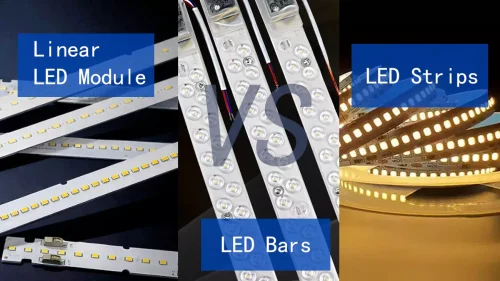
Choose the right DOB technology by first defining the finished luminaire’s operating conditions and measurable performance requirements, then matching the circuit architecture to them. At Higntek, we assess six key areas before narrowing down the options: application and target market, AC input and power quality, dimming and control, LED light quality, PCB space and thermal limits, and total luminaire cost. Each shortlisted design needs to meet these requirements under the actual operating conditions before the PCB is finalized.
We see the difference even between products with the same wattage. A 20 W ceiling light for a tightly controlled indoor application may prioritize a shallow housing and a lean BOM. A 20 W retail fixture running ten or more hours a day may put much more weight on low flicker, stable dimming, color quality, and operating temperature. This is why rated wattage alone cannot determine the right DOB architecture. So, the 20 W AC DOB LED rating describes the power level and input type, but it does not provide enough information to select the right DOB LED driver.
In our engineering assessments, we pay particular attention to how the LED string voltage, mains input range, enclosure temperature, and control requirements interact. These relationships often reveal design limitations that a nominal-power specification alone would miss.
Start With What the Light Actually Has to Do.
Start with the lighting application because it defines the operating conditions and performance priorities the DOB circuit must meet. Before discussing a DOB LED driver IC, we first establish where the luminaire will operate, how long it runs each day, whether users can touch accessible parts, how much airflow the enclosure provides, and which market the finished product will enter. Those conditions change the design priorities.
A compact residential lamp may be highly cost- and space-sensitive. Office and retail lighting often put more weight on flicker, dimming behavior, color consistency, and visual comfort. Outdoor and industrial lighting introduce harsher ambient temperatures, surge exposure, longer operating hours, and stronger protection requirements.
Target market belongs in this discussion from the beginning as well. A technically functional DOB LED module is not automatically a commercially usable one if its electrical performance does not match the regulations that apply to the finished lighting product.
We evaluate DOB suitability against the complete application, including its operating environment, installation conditions, expected service life, and target-market requirements. A circuit that performs well on the test bench still needs to meet its requirements inside the intended luminaire.
Write Electrical Requirements as Numbers, Not Adjectives.
Define electrical requirements through measurable limits and clearly stated test conditions rather than general performance descriptions. Many terms such as high PF, low THD, low flicker, stable output, and a wide input-voltage range sound reassuring, but they are poor procurement specifications until numbers and test conditions sit behind them.
A useful electrical brief should define at least the intended mains range, rated power, allowable power variation, power factor or displacement factor, harmonic requirements, flicker target, surge expectation, and any relevant current-regulation limits.
We also recommend checking these parameters under the operating conditions that matter to the finished product. A PF result at nominal voltage and full load, for example, does not automatically demonstrate equivalent performance across the entire input range or at reduced dimming levels. For example, current EU Ecodesign requirements for applicable mains LED light sources set minimum displacement factor according to input power. The requirement rises from DF ≥0.5 above 5 W to 10 W, to ≥0.7 above 10 W to 25 W, and ≥0.9 above 25 W. The same regulation specifies PstLM ≤1.0 at full load and SVM ≤0.4 for applicable products, with defined exceptions.
Harmonic emissions are a separate issue. IEC 61000-3-2 covers harmonic-current limits for equipment connected to public low-voltage systems with rated input current up to 16 A per phase and includes provisions for lighting equipment.
One distinction we always keep clear in our engineering assessments is that PF, displacement factor, and THD are related but not interchangeable. A DOB LED specification saying only “PF >0.9” does not automatically tell us whether the finished product will meet its harmonic-current requirement. When comparing suppliers, we therefore recommend requesting actual PF, displacement factor, and harmonic-current results under specified input-voltage and load conditions, rather than relying on a single headline figure.
Decide How the DOB LED Will Dim Before the PCB Is Fixed.
Define the dimming method, required operating range, and compatibility conditions before finalizing the DOB circuit and PCB. “Dimmable DOB LED” is not specific enough to design or approve against. Phase-cut dimming, 0-10 V, DALI, PWM, sensor control, and other schemes do not place the same requirements on the driver electronics. The project may also need a defined minimum light level, smooth startup, no visible stepping, stable low-end operation, or compatibility with a known control system.
This matters because a DOB LED light may perform cleanly at 100% output and behave very differently at 10%. And the U.S. Department of Energy also notes that temporal light modulation depends on the waveform delivered to the LEDs and may change with driver loading, dimming level, and the waveform supplied by the dimmer. From our engineering perspective, dimmer compatibility is a system-level result, not simply a feature listed on a DOB LED driver IC datasheet. The driver, LED load, dimmer, and control conditions all need to work together.
We therefore prefer a testable requirement such as “stable dimming from 10% to 100% under the specified control method” over a general “dimmable” claim. The former gives the DOB LED driver designer a clear performance target, while the latter leaves the most demanding part of the requirement undefined.
Do Not Ask the DOB LED Driver to Solve an LED Problem.
Separate LED-related light-quality requirements from driver-related electrical performance before deciding which parts of the module need customization. CRI, CCT, spectral distribution, and initial color consistency mainly depend on LED package selection, phosphor characteristics, binning, and optical design. The DOB LED driver more directly affects current stability and temporal light modulation. Thermal conditions then connect both sides because excessive temperature affects LED output and long-term stability.
That distinction becomes useful in real specifications. For a retail DOB LED light, for example, the requirement might include CRI ≥90, ≤3 SDCM color consistency, a defined CCT, and a measurable flicker limit. Those targets do not all belong to the DOB LED driver IC. They require LED selection, electrical design, PCB thermal performance, and optics to work together.
For projects where color rendition needs more analysis than a single CRI value provides, ANSI/IES TM-30 offers additional measures for color fidelity, gamut, and hue-specific changes. The point is not that every DOB LED project needs TM-30 testing. It is that the light-quality specification should reflect the actual application rather than collect impressive-looking numbers. In our design reviews, we keep the responsibilities of the LED source, driver circuit, and optical system distinct. This helps us identify whether a performance limitation comes from LED selection, electrical regulation, or optical design before recommending changes to the DOB module.
Treat PCB Space and Heat as the Same Conversation.
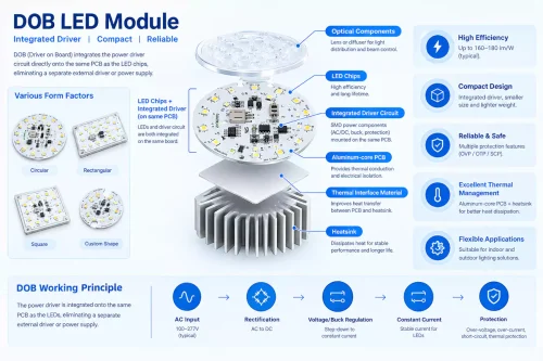
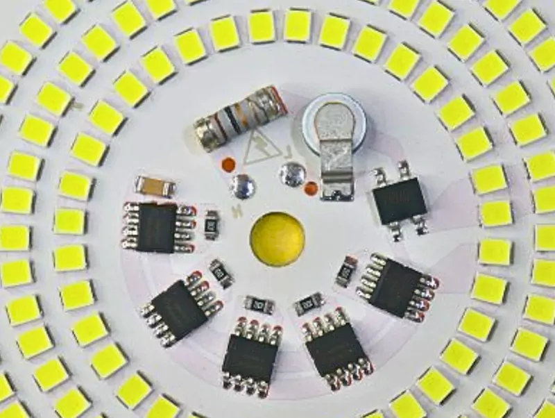
Evaluate PCB dimensions and thermal performance together. A smaller DOB board is only an advantage when the finished fixture can still dissipate heat within the required limits. One reason designers choose driver on board technology is space. Removing a separate driver enclosure can make a fixture thinner and reduce wiring, but moving the driver electronics onto the LED board also places more heat sources in the same mechanical area.
That creates a trade-off that is easy to miss during sourcing. For example, a smaller DOB PCB does not necessarily create a smaller finished luminaire. If the denser board requires a larger aluminum housing or more thermal mass to keep the LEDs and electronics within temperature limits, some of the apparent space saving has simply moved elsewhere.
This is why we normally look at the PCB and housing together. PCB material, copper distribution, LED placement, driver-component placement, thermal interface, available heatsinking area, and enclosure airflow all affect the usable thermal margin. In our engineering reviews, we pay particular attention to the hottest LED and driver locations, as well as the actual thermal contact between the PCB and luminaire housing. The substrate material alone does not determine how well the complete assembly manages heat.
At Higntek, our custom LED module engineering covers LED selection, electrical and PCB design, thermal-path optimization, prototype verification, and production rather than treating those as separate purchasing decisions. Depending on the project, PCB options include aluminum, copper, and FR-4 structures, with customized layout and thermal design. For a procurement team, the useful metric is therefore not simply “small PCBA.” It is the smallest LED lighting module that still meets the required electrical and thermal performance in the actual fixture.
Calculate Cost at Luminaire Level.
Compare DOB solutions by their contribution to the total luminaire cost, not by the quoted price of the DOB LED board alone. DOB technology can reduce BOM and assembly complexity, but the lowest DOB board quotation does not necessarily produce the lowest-cost lighting product.
The commercial comparison should include more than the DOB LED driver IC and LED count. Depending on the design, cost may also come from protection components, PCB material, thermal hardware, control circuitry, EMC measures, connectors, assembly, testing, certification work, and mechanical changes needed to accommodate the board.
There is also a development-cost dimension. A very aggressive low-component design may look attractive during quotation and lose that advantage after an extra PCB revision, repeated dimmer testing, additional EMI work, or a larger heatsink becomes necessary.
We recommend comparing shortlisted DOB solutions against the same functional specification, including light output, input range, dimming performance, protection requirements, and thermal limits. This makes it easier to see whether a lower initial BOM actually delivers a lower overall product cost. For that reason, we normally reduce the first-stage DOB decision to a project brief like this:
| What to define before choosing DOB technology | A useful procurement question |
|---|---|
| Core application | Where will the light operate, for how many hours, and under what ambient conditions? |
| Electrical input | What mains range and frequency must the AC DOB LED support? |
| Power quality | What PF/DF, harmonic, flicker, surge, and regulation targets must be verified? |
| Dimming/control | Which interface is required, and what minimum stable dimming level is acceptable? |
| Light quality | What CCT, CRI, color consistency, and TLM requirements actually matter to the application? |
| Safety/compliance | Which market and finished-product standards determine insulation, protection, and testing? |
| Thermal limit | How much temperature margin remains inside the real enclosure at worst-case operation? |
| PCB/mechanical space | What board dimensions and component-height limits are genuinely fixed? |
| Cost | What is the acceptable finished-product cost, not just the DOB PCB price? |
Once those answers are fixed, DOB technology becomes much easier to narrow down. More importantly, the team is choosing against a specification that can later be tested, quoted, and manufactured, rather than choosing a circuit because it looks simpler on paper. The next question is then much more specific – whether those project conditions point toward Linear DOB or Switching DOB.
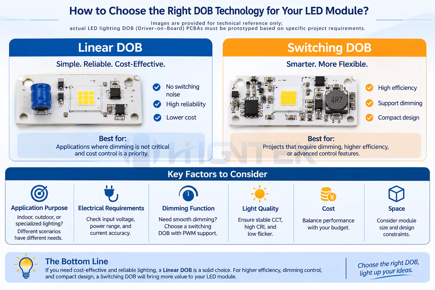
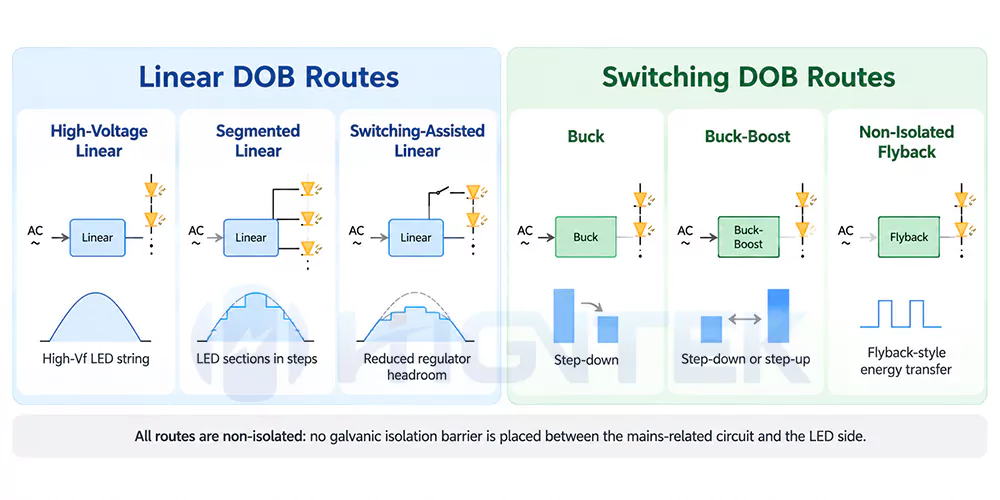
Choose Linear DOB when a defined mains range, compact circuitry, low component count, and simpler EMC work already meet the project targets. Choose Switching DOB when linear regulation starts consuming too much thermal margin, or when the project needs stronger efficiency and current regulation across changing electrical conditions. Click to learn more about our detailed analysis and explanation of DOB technology types for LED modules.
In our engineering assessments, we do not use a fixed wattage cutoff to make this decision. There is no universal rule such as under 20 W use Linear DOB and above 20 W use Switching DOB. We would not make a sourcing decision that way. A well-matched 25 W segmented Linear DOB may be perfectly workable, while a 15 W DOB LED inside a small sealed housing may benefit from switching regulation because even a few watts of extra driver loss matter.
The deciding factor is whether the selected architecture meets the electrical and thermal requirements with sufficient margin. We generally favor Linear DOB when its simpler circuit meets the targets comfortably. When linear losses start compromising temperature or regulation, we evaluate whether Switching DOB offers a better overall solution.
Choose Linear DOB While Simplicity Still Works in Your Favor.
Linear DOB makes the most sense when the LED load and AC input conditions can be matched closely enough that the regulating devices do not spend too much power as heat. For a linear regulating element, a useful first check is:
Power loss ≈ voltage dropped by the regulator × LED current
So a regulating path carrying 200 mA while dropping 15 V dissipates roughly 3 W at that operating point. An AC linear circuit does not stay at one voltage and current throughout the mains cycle, particularly in segmented designs, so this is not a complete efficiency calculation. It does explain why apparently small changes in LED string voltage can materially change board temperature.
High-voltage and segmented Linear DOB architectures work around this limitation in different ways. Segmented Linear DOB brings additional LED sections into conduction as the rectified mains voltage rises, making better use of the AC waveform and reducing unnecessary voltage across the regulating elements. That can produce better performance than the common assumption that “linear automatically means inefficient.”
A peer-reviewed IET study developed a 15 W sectional linear LED driver that achieved more than 0.9 power factor and approximately 90% efficiency with few peripheral components after optimizing the LED distribution between segments. The same research showed an important trade-off that purchasing specifications often miss. Increasing the LED count could reduce dropout loss and raise efficiency, but it could also reduce conduction duty cycle and output power, so the LED string configuration had to be optimized rather than simply maximized. This is also why, when we evaluate an AC DOB LED board, we look at the LED configuration and regulator operating conditions together rather than judging efficiency from the topology alone.
From our engineering perspective, Linear DOB is usually worth keeping when the following conditions are met:
- the product serves a relatively predictable mains range;
- the LED-string configuration keeps regulator losses under control;
- prototype temperatures still have healthy margin at high-line and maximum ambient conditions;
- a small PCB and low component count have meaningful commercial value;
- the required current regulation is achievable without adding excessive circuitry;
- avoiding a high-frequency switching stage reduces EMC complexity.
There is also switching-assisted linear DOB. It belongs to the Linear DOB family, but its added switching function can improve power handling or waveform utilization. We evaluate it as a distinct design option rather than assuming it has exactly the same characteristics as conventional high-voltage or segmented linear circuits. Once switching action is introduced, part of the usual EMI and component-count advantage begins to narrow.
For more precise current regulation, choose a Switching DOB.
Switching DOB becomes the stronger option when preserving a simple linear circuit forces compromises elsewhere in the luminaire. Buck DOB, Buck-Boost DOB, and related switching architectures transfer energy through controlled high-frequency switching. Depending on the selected topology and operating point, this can maintain higher conversion efficiency and tighter LED-current regulation than dissipative linear regulation.
In our project evaluations, we start considering a switching DOB solution when one or more of the following conditions appear:
- linear-stage losses are pushing the board or DOB LED driver IC too close to its thermal limit;
- the fixture has little heatsinking area available;
- the required electrical operating window is difficult to cover efficiently with the proposed linear arrangement;
- LED current or power changes more than the product specification allows as mains conditions move;
- every watt of driver loss noticeably affects luminaire efficacy or enclosure temperature;
- the performance gain is large enough to justify additional magnetic components, PCB area, and EMC work.
The last point matters. Switching DOB is not automatically the “better” DOB technology simply because its conversion efficiency can be higher. Switching nodes create conducted and radiated EMI that need deliberate PCB layout and filtering. Inductors and other power-stage parts increase BOM and consume space. More components also mean more variables to qualify during sourcing and production.
| Project condition | Lean toward Linear DOB | Lean toward Switching DOB |
|---|---|---|
| Electrical operating window | Predictable enough for good LED/input matching | Broader or harder to regulate efficiently |
| Linear-stage loss | Remains comfortably within thermal budget | Begins consuming too much thermal margin |
| Efficiency requirement | Target is already achievable with margin | Linear losses prevent the target from being reached |
| LED current regulation | Stable enough under specified conditions | Tighter regulation across changing conditions matters |
| PCB/component count | Minimum parts and compactness are priorities | Additional power-stage components are acceptable |
| EMC effort | Simpler high-frequency environment is valuable | Project can support switching layout and filtering |
| BOM strategy | Extra circuitry offers little product-level benefit | Added BOM solves a measurable performance problem |
| Best fit | Simplicity still satisfies the specification | Electrical or thermal requirements have outgrown that simplicity |
One boundary should remain clear. Linear versus Switching describes how the DOB circuit regulates power; it does not tell us whether the circuit is isolated. Most Linear DOB solutions are non-isolated, but Isolated Linear DOB also exists. Switching DOB may likewise be isolated or non-isolated. Those safety architectures need their own decision criteria.
For us, the practical rule is to stay with Linear DOB while simplicity still leaves enough margin. Once that simplicity starts costing too much in heat, efficiency, or regulation, Switching DOB becomes the more sensible engineering choice. The best DOB technology is not the circuit with the fewest parts or the most sophisticated DOB LED driver IC. It is the one that reaches your product targets without paying for complexity the luminaire does not need.
A 22 W Project Where Thermal Testing Changed Our Decision.
We encountered this trade-off during the development of a 22 W recessed commercial downlight for a European lighting customer. The fixture had to operate from 220-240 V AC, and the customer wanted the LEDs and DOB LED driver on one compact aluminum PCB because the ceiling housing left very little depth for a separate power supply. Our first segmented Linear DOB prototype reached the required light output and kept the electronic BOM simple. At 230 V and room temperature, the result looked acceptable. However, the high-line thermal test revealed a limitation that had not appeared during the initial evaluation. With the complete light engine operating at 240 V AC and 40°C ambient, the hottest point around the linear driver section reached approximately 84°C after temperature stabilization. Input power was about 25.4 W at the target LED operating point.
We then redesigned the power section around a Switching DOB architecture, keeping the LED load and mechanical envelope essentially unchanged. Under the same operating condition, input power fell to around 23.8 W, and the hottest measured driver-area point settled near 72°C. Under the same test conditions, the revised design reduced input power by approximately 1.6 W and lowered the measured hotspot temperature by about 12°C.
The electronics BOM increased by approximately 11%, and we needed additional PCB work around the switching loop and EMC components. We kept the switching version anyway. For this project, the additional electronics cost was justified by the improved thermal performance and greater operating margin inside the shallow fixture. We would not have added the switching stage if the original Linear DOB prototype had maintained an acceptable temperature under the same high-line test. That is the decision we want prototype data to make for us.