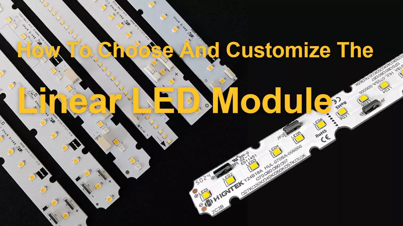
Over the past thirteen years of LED module engineering work with clients across hospitality, retail, signage, and architectural facade projects, I have observed that buyers in linear LED module procurement conversations consistently focus on the same three questions: how many lumens, what CCT, and what is the cost per meter. That is the entirety of most buying conversations. None of those three questions reliably predicts what actually goes wrong in year four.
Linear LED modules have quietly become the workhorse of commercial lighting. They replaced fluorescent tubes in office coves, took over architectural facades from neon and cold cathode, and now anchor everything from hotel lobbies to retail displays to outdoor signage. The wide range of form factors and the high efficiency gains over older lighting have made them the default light engine for most modular linear LED lighting designs today. Energy efficiency improvements in the 50-70% range over the fluorescent fixtures they replaced are common, which is part of why modular linear LED lighting projects pay back their initial cost in just a few years.
The catch is that picking the right linear LED module is no longer a one-question decision. It is a stack of decisions that interact: which module, what driver, which control protocol, which supplier, and whether to specify a standard part or commission a custom design. If the entire decision-making process is correct, the luminaires will still meet lighting needs even ten years later.
Five questions come up in almost every linear LED module sourcing conversation we have at Higntek: how to choose the right module for a project, when to customize rather than buy standard, how to vet a manufacturer worth trusting with long-term work, what the custom module development process actually looks like end to end, and what really drives the cost of a linear LED module in 2026. The sections below are built from the questions specifiers, integrators, and lighting designers ask us most often, with the answers we wish more procurement teams asked for up front.
How to Choose the Right LED Linear Module?
In our experience, what goes wrong in year four traces back to one of seven decisions that got rubber-stamped at the same time as the module pick: application scenario, core optical and electrical metrics, driver compatibility, dimming and control protocol, certification stack, long-term total cost of ownership, and the supplier behind the product. These are not seven separate choices. They are one connected system, and the spec sheet tells you about exactly one piece of it.
Application Scenarios.
The installation environment determines which structural material, IP rating, and substrate class are even on the table — before lumen output, CCT, or driver type enter the conversation. Get this wrong and every downstream specification decision is built on the wrong foundation.
A module with a color temperature of 4000K and a luminous efficacy of 150 lm/W might look beautiful in an office recess, but it’s not ideal for a five-star hotel lobby requiring smooth dimming to 1% brightness and a warm color tone. An award-winning high color rendering index (CRI) linear LED module installed in flagship retail stores would overheat within two summers if installed in an outdoor signage recess without proper heatsinks and sealing. Linear lights designed specifically for office recess integration have significantly different heat dissipation performance compared to the same module installed in sealed signage profiles. The performance of multiple linear modules running in series also differs from the performance of a single module on a test bench.
For general commercial interiors — retail, hospitality, corporate — the governing constraint is usually the cavity depth and heat path. Most slot-in linear fixtures assume the module back makes direct contact with an aluminum housing that doubles as a heat sink. When that contact is broken by poor fitment or an air gap, junction temperature climbs and lumen depreciation accelerates. In practice, the difference between a 0.2 mm air gap and direct contact can shift the L70 endpoint by 8,000 to 12,000 hours on a high-power module.
Medical cleanrooms introduce a different constraint set. Surfaces cannot trap particulates, so any module with exposed pin connectors or irregular lens geometry gets rejected at the facility design stage. In high-temperature industrial environments (such as foundries, equipment near kilns, and continuously operating factory lighting) or high-power lighting applications, aluminum-based PCBs are better suited to handle steady-state heat loads. When peak thermal cycling is extreme, copper-based PCBs come into play because copper’s thermal conductivity (approximately 380–400 W/m·K) is significantly higher than aluminum’s (approximately 140–200 W/m·K), a difference that is clearly reflected in actual junction temperature data under load.
Outdoor linear applications add UV stability and ingress protection. IP65 is the practical minimum for covered outdoor canopy lighting; anything directly rain-exposed needs IP67 or above, and the module-to-driver sealing must be rated accordingly. Specifying an IP67 module mated to an IP54 driver enclosure is a system-level mistake that shows up 18 months into operation, not at commissioning.
Core metrics..
Key performance indicators for linear LED modules include luminous efficacy, CRI, CCT, SDCM, lifespan, color dimming functionality, electrical specifications, and dimensions.
However, many specifications are not fixed industry standards. Higntek conducts systematic engineering design during the engineering phase based on each customer’s application and project requirements, rather than using a one-size-fits-all approach. Once the LED module engineering design is finalized, the focus is on the 5 specifications most important to the customer:
- CCT selection — warm white (2700–3000 K), neutral white (3500–4000 K), or cool white (5000–6500 K) — follows application logic, not preference. We control the color temperature deviation of batch-to-batch linear LED modules to within ±50K. Neutral white dominates commercial and industrial environments because it supports visual acuity without the harshness of cool white at equivalent illuminance levels.
- Luminous efficacy, or lm/W ratio, determines the amount of light produced per watt of input power. current LED module luminous efficacy is generally in the range of 140-180 lm/W; target values depend on the application and the customer’s energy budget; higher luminous efficacy means lower power consumption for the same brightness. Differences in luminous efficiency determine the number of drivers, wiring length, and operating costs required throughout the system’s lifespan. Higntek’s HUL series boasts a luminous efficiency of up to 265 lm/W. In a lighting project with 500 modules, a difference of 30 lm/W not only impacts electricity costs but also necessitates adjustments to different circuit dimensions to ensure stable driving.
- SDCM (Standard Deviation of Color Matching) is a metric that measures whether adjacent modules in the same linear arrangement have the same color. When SDCM ≤ 3, the human eye cannot reliably perceive this difference, which is suitable for high-quality linear lighting. However, when SDCM reaches 5 or 6 (which is the actual shipment value for a significant portion of standard production modules), slight differences can be detected upon close comparison, easily affecting the sense of sophistication in a space. For high-end retail, hotel, or museum lighting, SDCM ≤ 3 is a mandatory requirement.
- The same applies to CRI and R9: CRI ≥ 90 matters wherever color affects purchase decisions or clinical judgment, and R9 > 50 is the specific threshold for saturated red rendering — relevant in food display, cosmetics, and surgical environments where skin tone and product color accuracy are operationally significant.
- On lumen maintenance, LM-80 test data combined with TM-21 projection gives a defensible L70 figure at a specific junction temperature. A module rated L70 > 50,000 hours at Tj = 85°C may reach that point at 35,000 hours if the installation’s thermal path keeps Tj running at 95°C — a discrepancy that only surfaces after the warranty period ends.
Driver.
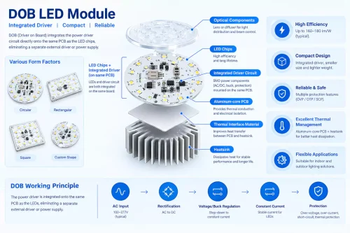
Three driver architectures cover the LED linear module market: constant-current (CC) external drivers, constant-voltage (CV) external drivers, and DOB (Driver-on-Board) modules that integrate the driver circuit directly onto the PCB. The right choice depends on the installation’s electrical infrastructure, dimming requirements, and thermal constraints — not catalog convenience.
- CC drivers hold a fixed output current — typically 350 mA, 500 mA, 700 mA, or 1050 mA — and are preferred where consistent lumen output across a long daisy-chain matters more than wiring simplicity.
- CV drivers, most commonly 24 VDC, are simpler to configure but introduce lumen variation across modules in longer runs as voltage drops along the cable. For more details on the differences between constant current and constant voltage, please visit our LED lighting module technology blog.
- DOB modules eliminate the external driver entirely, integrating rectification and current regulation onto the module PCB — practical for retrofit scenarios where driver enclosure space is limited. Higntek’s DOB driverless LED module is designed to ensure the stable operation of such simplified lighting modules.
On driver output parameters: load drivers to 70–80% of rated capacity maximum. A driver at 100% rated load runs hotter, degrades faster, and becomes the first component to fail in an otherwise well-designed system. Flicker performance — percent flicker and flicker index per IEEE 1789-2015 — requires measured test report values in medical, educational, and machine vision environments; a datasheet label is not a substitute.
Dimming Control Protocol.
LED linear modules support a range of dimming protocols: 0-10V, DALI (IEC 62386), PWM, TRIAC / Phase-Cut, ELV (Electronic Low Voltage), Switch dimming, and DMX/DMX512, plus wireless variants (Zigbee, Bluetooth Mesh). Protocol selection is determined by the building management system already in place, the number of addressable zones, and whether the installation requires bidirectional feedback — not by which protocol the module catalog defaults to.
- 0-10V is the baseline for single-zone applications — low cost, simple wiring, dims to approximately 10% output. For projects that stop there, it is sufficient. For anything involving multiple zones, fault monitoring, or integration with a building management system, it is the wrong protocol regardless of cost.
- DALI (IEC 62386), maintained by the DALI Alliance, is the protocol of choice for large-scale commercial and smart building installations. Unlike every other protocol in this list, DALI is bidirectional: each addressed driver reports live status — operating hours, fault state, lamp-hours — back to the controller.
- PWM dimming modulates power at fixed frequency to control average light output; it is precise and compatible with many drivers but requires attention to frequency selection in flicker-sensitive environments.
- TRIAC and Phase-Cut are phase-cutting protocols designed for trailing- or leading-edge wall dimmers — common in retrofit residential and small commercial applications, less suitable for long cable runs or precision control.
- ELV works similarly to trailing-edge TRIAC but is designed for electronic low-voltage transformers. Switch dimming uses simple on/off switching sequences to step through preset lumen levels, requiring no dedicated dimmer hardware.
- DMX512 provides 512 individually addressable channels per universe, the standard for architectural and entertainment lighting where scene programming and per-fixture control matter more than energy reporting.
We will be providing a detailed professional blog post on LED module dimming control protocols to help you better understand them. Stay tuned.
| Protocol | Signal type | Min. dim level | Bidirectional | Best fit |
|---|---|---|---|---|
| 0-10V | Analog | ~10% | ✗ | Single-zone commercial, simple retrofit |
| PWM | Digital pulse | ~1% | ✗ | Precision dimming, driver-integrated control |
| TRIAC / Phase-Cut | Phase-cut AC | ~15–20% | ✗ | Residential, small commercial retrofit |
| ELV | Trailing-edge AC | ~10% | ✗ | Electronic low-voltage transformer systems |
| Switch dimming | On/off pulse | Preset steps | ✗ | No-dimmer-hardware retrofit, preset scenes |
| DALI-2 (IEC 62386) | Digital bus | 0.1% | ✓ | Large commercial, smart building, emergency lighting |
| DMX / DMX512 | Digital | 0% | ✗ | Architectural, entertainment, façade |
| Zigbee / BT Mesh | Wireless digital | 0.1% | ✓ | Wireless retrofit, no new bus wiring |
Certifications and compliance.
UL listing is mandatory for North American commercial and specified applications. RoHS and REACH compliance are the baseline for EU market access. For medical facility applications, ISO 13485 certification at the manufacturing level indicates the quality management system meets medical device manufacturing standards. Most LED module suppliers do not hold ISO 13485; it is a meaningful differentiator in healthcare and pharmaceutical facility projects.
LM-80 data should be treated as a technical document requirement. The test must be conducted at the specific operating current and at minimum three junction temperature points over 6,000 hours. Any supplier unable to produce the actual LM-80 test report — not a summary — is either not testing at required conditions or inflating projected life numbers.
ISO 9001 and ISO 14001 are table stakes for specification-grade supply; projects with government, institutional, or ESG-reporting clients frequently require both as a minimum. A supplier without these certifications is not disqualified from producing a functional module — but they are disqualified from many of the projects where module performance matters most.
Long-term value.
Acquisition cost is one line in the project budget. The fully-loaded comparison — module price + driver + installation labor + energy consumption + maintenance over 10 years — consistently shows that a higher-efficacy, longer-life module at a 20–30% unit price premium delivers lower total cost in most commercial installations beyond year three.
A module at 225 lm/W versus 150 lm/W changes more than the energy bill. At scale, the difference in driver count and wiring runs required to hit a target illuminance is a capital cost difference, not just an operating one. A verified L70 > 60,000 hours at operating Tj has a different maintenance schedule than L70 = 30,000 hours — and in any facility where lamp replacement requires a lift or system shutdown, that schedule difference has a hard dollar value.
Color maintenance — holding CCT over service life without drifting toward green or pink — is separate from lumen maintenance. Modules with poor phosphor or thermal management drift visibly in color at 20,000–30,000 hours even when lumen output is still within spec.
Supply chain capability.
A specification is only as reliable as the supply chain executing it. The three variables that most consistently separate dependable suppliers from unreliable ones are: documented on-time delivery rate, verifiable Tier-1 chip traceability from Lumileds, Nichia, or Cree, and SMT equipment specification — because placement accuracy determines whether the production batch matches the approved sample.
At Higntek, 25 Samsung SMT machines across 8 fully automated lines run 100% AOI and X-ray inspection on every production batch. The 99.38% on-time delivery rate is a documented production metric. Chip supply from Lumileds, Nichia, and Cree comes with traceable certification, which means chip specification changes between sample approval and mass production do not happen silently — a protection that matters when a lighting specification is locked at tender stage.
Working through these dimensions in sequence — application environment → photometric specs → driver type → dimming protocol → certifications → long-term cost → supply chain verification — eliminates most specification errors before they become project problems.
How Do You Customize Linear LED Modules?
Standard modules cover most projects. The ones they don’t cover tend to be the ones where the cost of getting it wrong is highest — non-standard fixture geometries, regulated medical environments, outdoor installations with conflicting thermal and sealing requirements. That’s when customization stops being an option and becomes the engineering solution.
Retail slot lighting — non-standard cavity, visible splice gaps. A high-street fashion chain specified a continuous 2,400 mm illuminated ceiling slot across 34 stores. Standard 300 mm and 600 mm modular linear LED lighting modules left splice gaps every module length — detectable as dark bands under the diffuser at certain angles. The cavity width was also 4 mm narrower than any catalogued module. The fix was a purpose-built module at the correct width and length, with matched end-cap geometry to eliminate the gap at junctions. No standard product resolved both constraints simultaneously.
Surgical suite — CRI, R9, and SDCM as clinical requirements. In surgical environments, light quality is a patient safety parameter. CRI ≥ 95 and R9 > 90 are common specification floors; SDCM ≤ 3 is required so color rendering is consistent across the entire ceiling plane. Manufacturing to these tolerances requires chip-level binning tighter than standard commercial production, combined with a quality system audited for medical device manufacturing. Higntek’s ISO 13485 certification covers exactly this — the quality system governing design, assembly, inspection, and documentation meets medical-grade manufacturing standards, not just general commercial ones.
Outdoor linear fixture — thermal stress vs. potting compound conflict. An outdoor architectural linear project specified IP67 protection with a fully potted module cavity. Standard silicone potting compound trapped heat that a conduction path to the aluminum extrusion would otherwise dissipate. At 40°C ambient with solar loading, junction temperature inside the potted cavity exceeded safe operating range. Resolution required redesigning the module’s thermal pad interface and using selective potting — protecting electrical connections without encapsulating the heat-generating components. Standard catalog modules do not offer this.
When is a standard module enough vs custom design?
Standard linear LED modules are the right call when the project’s spec sits comfortably inside what catalog parts already offer: common dimensions, mainstream CCT and CRI values, mid-range driver compatibility, no unusual structural or environmental constraints. The practical rule: if the project has one constraint a standard LED lighting module cannot meet, workarounds usually exist. If it has two or more — non-standard geometry plus a tight SDCM requirement, for instance — the accumulated compromise cost of forcing a standard LED lighting module typically exceeds the tooling investment for a custom one.
Custom design and manufacturing are required when an LED lighting module meets any of the following conditions:
- Mechanical constraints.
The mechanical envelope (dimensions, mounting interface, and structural form factor) does not align with any available catalog option. - Optical performance requirements.
Optical targets exceed standard binning capabilities, such as tighter SDCM tolerances, higher CRI requirements, or specific luminous efficacy and brightness targets defined by application needs. - Electrical and driver integration requirements.
Electrical customization is required when standard drivers cannot efficiently support the application. This includes non-standard voltage/current combinations, custom power factor or efficiency targets, AC LED module architectures for retrofit applications, and integration of dimming protocols such as DALI-2, D4i, or DMX. In such cases, driver matching and electrical layout are handled as part of the module-level engineering process.
| Decision factor | Standard module | Custom design |
|---|---|---|
| Physical fit | Fixed lengths (300/600/1200 mm) | Any dimension; cavity-matched geometry |
| Development time | Ships from stock or 1–2 weeks | 15 days standard; complex ~5 weeks |
| Unit cost | Lower per piece | Higher per piece; amortized over MOQ |
| MOQ | 1 piece to low hundreds | Typically 200–500 pcs minimum |
| Photometric spec | Catalog CCT/CRI bins | Project-specific CCT, CRI, SDCM ≤ 3, R9 |
| Performance ceiling | Fixed at catalog maximum | Optimized to application thermal and optical targets |
If your project hits two or more constraints in the right column, a standard module will require compromises that show up either at installation or over the service life.
Full-stack customization at Higntek.
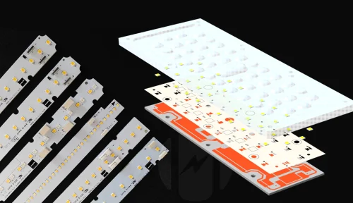
On a typical custom project, Higntek’s engineering team works across the full module stack rather than substituting one component at a time. The scope covers dimensions and structure (length, width, mounting hole pattern, end-cap geometry, connector position); optical specification (CCT from 2700 K to 6500 K, CRI grade up to 95+, R9 target, SDCM tolerance down to ≤ 2, lens beam angle from 15° to 120°); driver and electrical requirements (input voltage 12–48 VDC or AC mains, CC or CV topology, output power, dimming interface); and connection interface (connector type, pin-out, wire gauge, and harness length matched to the OEM’s production line).
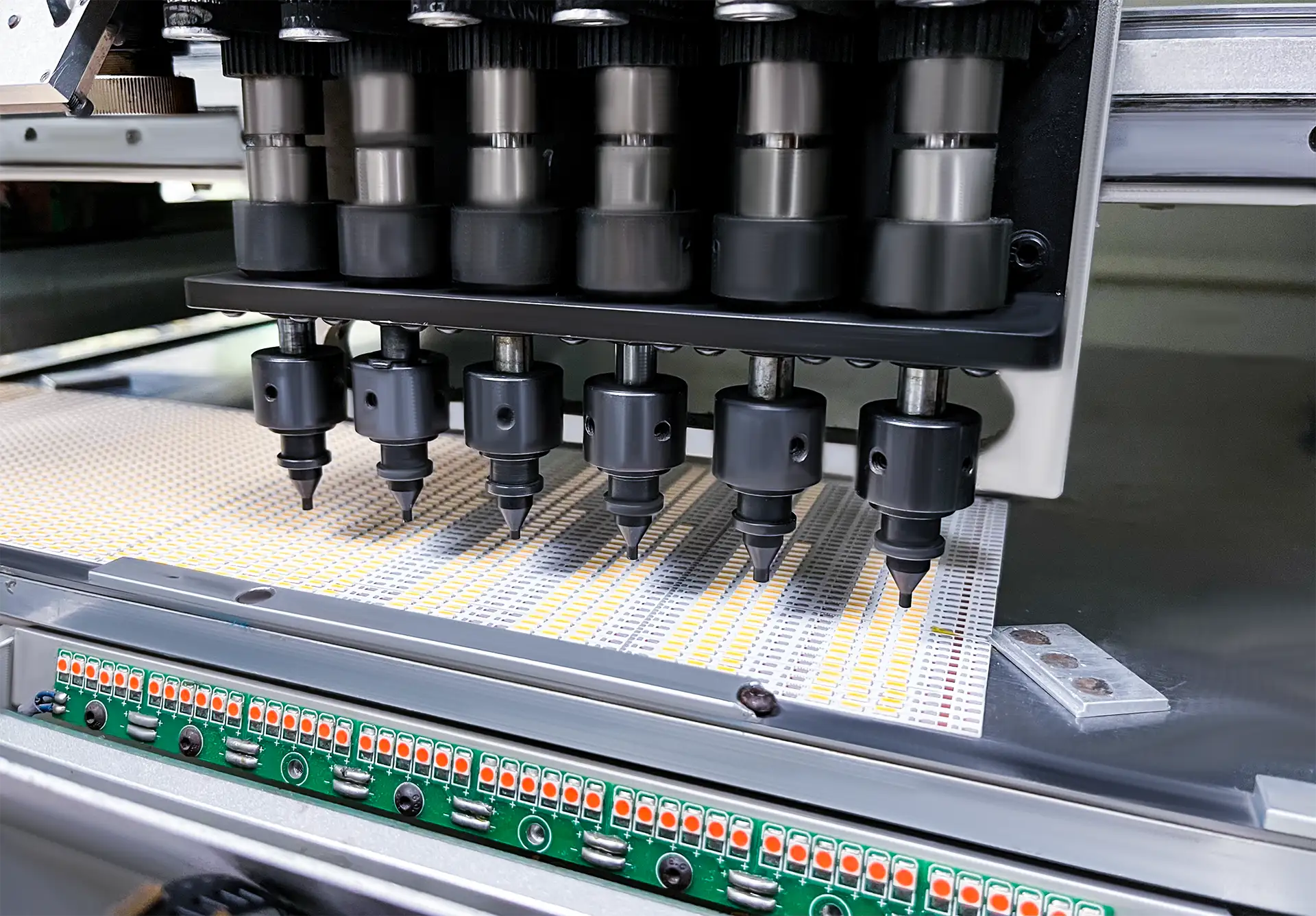
Production runs on 25 Samsung SMT machines across 8 fully automated lines, with 100% AOI and X-ray inspection on every batch. Standard custom projects complete prototyping in 5–7 days and reach production-ready sign-off within 15 days — covering requirements engineering, design, prototype build, and test, not just assembly.
A module engineered to the project’s actual constraints performs predictably over its service life. Higntek’s one-stop engineering-to-production service closes the gap between specification and delivery — from the first technical brief to certified mass production, without handing the project between separate design and manufacturing organizations.
How Do You Choose a Reliable Linear LED Module Manufacturer?
A reliable manufacturer is identified not by factory size or brand name, but by whether they can demonstrate system-level engineering capability — and back it with documented production data. The four capabilities that consistently separate engineering-grade suppliers from assembly-grade ones are: system design integration, thermal management verification, genuine ODM scope, and production-level inspection infrastructure.
System engineering design capability.
A module is a system: PCB substrate, LED array, optics, and driver all interact thermally and electrically. A manufacturer that sources these components separately and assembles them to order is not an engineering partner — they are a contract assembler. Thermal and electrical mismatches between independently sourced components are the most common root cause of premature lumen depreciation and driver failure in the field.
Before establishing a collaboration intention, several engineering questions need to be raised: Can the manufacturer simultaneously optimize PCB copper foil weight, LED forward voltage tolerance, and driver output curves in a single design? If the answer is simply “match the driver to the selected lighting module,” then it’s merely assembly. A manufacturer with true engineering capabilities will perform thermal resistance modeling, luminous flux prediction, and electrical engineering design analysis before prototyping.
Thermal management experience.
Junction temperature governs everything: lumen output, color stability, L70 lifespan, and driver longevity. Every 10°C rise above the LED’s rated Tj accelerates lumen depreciation — a relationship documented in LM-80 test data but routinely ignored in standard procurement.
Ask for the junction-to-ambient thermal resistance (Rθja) for the module at rated operating current. A manufacturer with real thermal management capability will have this measured, not estimated. Request the full LM-80 report — not a marketing summary — showing flux maintenance at 55°C, 85°C, and the manufacturer’s third temperature point across the full 6,000-hour test window. A supplier unable to produce this document either does not hold the data or is sourcing chips outside the Tier-1 supply chain where this testing is standard. Higntek conducts corresponding tests and issues test reports for each LED module project.
OEM and ODM support.
OEM capability means building to your specification. ODM capability means designing from a brief. Most mid-tier suppliers offering “OEM/ODM” only mean the former. Genuine ODM capability requires an in-house engineering team that has taken projects from schematic to mass-production-ready tooling. Ask for examples of completed ODM projects — the brief, the engineering challenge encountered, and how it was resolved — rather than accepting a factory tour as evidence of capability. If a supplier cannot describe a specific problem they solved in a past ODM engagement, they have not done ODM work at the engineering level.
Quality management and testing infrastructure.
ISO 9001 is the baseline and not a differentiator on its own. AOI catches solder bridges, insufficient solder volume, tombstoned components, missing parts, and polarity reversals immediately after reflow — defects that pass visual inspection at production speed but fail under thermal cycling in service. X-ray inspection can detect solder joints that are inaccessible by optics. Higntek performs 100% AOI and X-ray inspection on every production batch (rather than statistical sampling), which is equivalent to making a structural commitment that sampling inspection cannot match.
At Higntek, 25 Samsung SMT machines across 8 fully automated lines run 100% AOI and X-ray on every batch. Thirteen years of engineering experience across 600+ completed solutions and 1,500+ design variants, combined with a 99.38% documented on-time delivery rate, means the production system is calibrated to hold specification at volume, not just at prototype. ISO 9001, ISO 13485, and ISO 14001 certifications cover quality, medical-grade manufacturing, and environmental management — the combination specification-grade buyers and regulated-industry clients require.
The four capabilities above — system engineering design, thermal management with real data, genuine ODM scope, and production-level inspection infrastructure. This distinguishes manufacturers who can support lighting system design and development from those who can only fulfill simple catalog orders.
How Does Custom Linear LED Module Development Work?
A custom LED linear module project at Higntek moves through five engineering stages — requirements analysis, design, prototyping, testing, and mass production — with a zero-defect-at-shipment target governing every handoff. Standard projects reach production-ready sign-off within 15 days.
Requirements analysis and feasibility review.
Every project opens with a structured technical brief: installation geometry, target illuminance and uniformity ratio, CCT and CRI requirements, input voltage and dimming protocol, thermal environment, and certification constraints for the destination market. This stage surfaces conflicts before any design work begins — a module specified at 48 VDC constant voltage into a fixture cavity with no thermal conduction path to aluminum will not meet its L70 target regardless of chip quality. Catching that in the brief costs nothing; catching it after prototype tooling costs time and money.
Our feasibility assessment also determines the PCB substrate at this stage: FR-4 for cost-efficient standard commercial applications, aluminum-base for steady-state thermal loads, copper-base where peak junction temperature targets require thermal conductivity above what aluminum delivers.
Electrical and mechanical design.
With thermal budget and electrical parameters confirmed, the engineering team co-develops PCB layout, LED array configuration, and driver specification as an integrated design. PCB copper weight is chosen to minimize trace resistance under full rated load; LED forward voltage tolerance windows are matched to the driver’s output regulation range; driver derating is calculated at the installation’s maximum ambient to keep operation below 80% of rated load.
Mechanical design fixes the module’s physical footprint — length, width, mounting hole pattern, end-cap geometry, and connector position — to the fixture’s actual cavity dimensions. For OEM programs, this includes mechanical interface drawings reviewed against the customer’s fixture tooling before prototype release. A connector position change requested after tooling is cut costs 3–5× more than the same change made at this stage — which is why the mechanical review against customer tooling happens before prototype release, not after.
Prototype build and verification.
Prototype assembly runs on the same Samsung SMT equipment used for mass production — not a manual prototype bench — because placement accuracy and solder joint quality on the prototype must replicate what mass production will deliver. During reflow, AOI immediately flags solder bridges, insufficient solder volume, tombstoned components, and polarity reversals at sub-0.1 mm imaging resolution. X-ray follows for packages and chip-on-board arrays, verifying solder joint voiding and via fill quality in thermal relief structures. Cold joints that pass room-temperature electrical continuity test will develop open circuits under thermal cycling in service — X-ray at prototype stage is the gate that prevents field failures.
Reliability testing and Tj validation.
Prototype testing is not a pass/fail electrical check. The module operates at rated current in a controlled thermal environment while junction temperature is measured to verify that actual Tj matches the design model at the installation’s expected ambient. A module that meets lumen output spec but runs 12°C above modeled Tj in the prototype test will deliver significantly shorter L70 life than specified. That discrepancy is corrected at prototype stage, not diagnosed after 20,000 field hours.
Electrical stability testing covers input voltage variation, load transient response, and dimming linearity across the full protocol range. Any deviation from the driver’s output regulation curve under transient load — a condition that frequently triggers visible flicker in PWM-dimmed systems — is resolved before production release.
Mass production and delivery.
Production runs across 8 fully automated SMT lines with 25 Samsung SMT machines in parallel — the configuration that enables the 15-day standard custom cycle even when multiple projects run concurrently. Every batch ships with full traceability documentation: chip lot certificates from Lumileds, Nichia, or Cree; AOI and X-ray inspection records; electrical test data per unit; and certification compliance documentation for the destination market.
The engineering file package — schematics, PCB Gerbers, BOM with component lot traceability, and test records — stays on file. Repeat production runs reproduce the original specification exactly, without re-validation. For buyers running multi-year rollout programs across multiple sites, this means the 200th batch matches the first one — without re-submitting samples for approval or absorbing the schedule risk of a re-qualification cycle.
Higntek’s role in a custom program is engineering partnership from technical brief to certified mass production, with the documentation chain to prove every unit shipped matches what was tested.
What Factors Determine the Cost of a Linear LED Module?
The most common problem in LED linear module procurement is that buyers are often not focused on the final cost. The cost of an LED lighting module depends on the intersection of seven variables: LED chips, driver & dimming requirements, PCB, optical lenses, other electronic components and material requirements, size, and quantity.
In most cases, the initial unit price of an LED lighting module is easy to compare, but the cost of field failures 2-3 years after installation is also a concern for buyers focused on long-term effects—including energy consumption, lift rental, labor, downtime, module replacement, and reputational damage in the market.
- LED Chip Specifications.
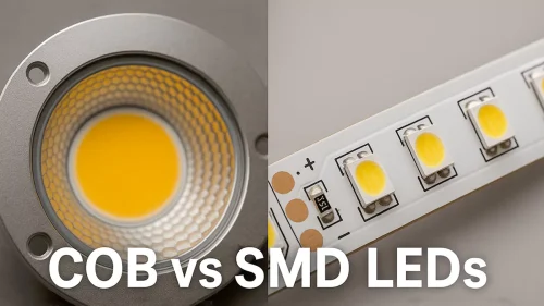
LED chips are the largest single cost variable. High-quality LED chips have more stringent forward voltage ratings, higher luminous efficiency, proven LM-80 lumen maintenance data, and more stringent color ratings, resulting in stable light performance and energy-saving goals. We will select the appropriate LED model (2835, 3030, 3535, 5050, etc.) from our hundreds of parts library based on customer needs and electrical design parameters. PCB.
As the operating substrate of LED lighting modules, the PCB material and manufacturing process determine operational stability and heat dissipation. FR-4 is the lowest-cost substrate suitable for linear LED modules in standard commercial applications, with a thermal conductivity of only 0.3-0.4 W/m·K. Aluminum-based MCPCBs are currently the most widely used in the lighting field, but their thermal conductivity is 120-200 W/m·K. Copper-based PCBs have thermal conductivity of up to 380–400 W/m·K, suitable for outdoor components subjected to solar radiation or continuous high-temperature environments. Choosing a PCB substrate solely based on cost rather than junction temperature (Tj) modeling is a poor approach: components operating on FR-4 substrates, even at operating temperatures 15°C higher than the design junction temperature, will only have a lifespan (L70) of 60–70% of the design lifespan.
During the thermal management design process, our engineers add additional heat dissipation holes to the PCB and optimize trace width, trace spacing, and copper thickness to achieve stable lighting.Driver complexity and dimming protocols.
As mentioned earlier, current LED lighting modules offer three types of drivers and diverse dimming technologies. Each development of a lighting LED module requires technical harmonization of driver technology and dimming functionality.
For example, a constant-voltage 24VDC driver and a DALI-2 addressable driver with bidirectional communication and an onboard microcontroller are not the same price. The cost of the DALI-2 reflects protocol certification, additional electronic components, and firmware verification, while 0-10V analog control does not require these.Optical Components.
There are two main types of optical components in LED lighting modules—lenses & reflectors and diffusers. This is because controllable beam control or uniformity requirements cannot be achieved solely with an LED array. These optical components increase the cost of the LED module, material costs, and assembly steps.Structural Dimensions.
The greater the deviation of the LED lighting module from the standard (Zhaga) PCB size, the higher the unit cost. Non-standard LED lighting modules require custom mounting clips, zero-gap end cap geometry, and non-standard connector positions. Highly customized lengths, non-standard wiring configurations, or complex shape cuts incur higher costs than standardized LED modules.Order Quantity.
Mass production is key to breaking down all fixed production costs. Whether the order quantity is 200 or 2000 units, non-recurring engineering costs (NREs) for molds and engineering are the same. These costs significantly increase the cost per PCS with 200 orders; however, they become negligible with 2000 orders. For most commercial linear modules, the break-even point between standard catalog pricing and the total cost of a customized module is between 1000 and 3000 modules. When the production volume exceeds this threshold, the cost of customized LED lighting modules will be very close to that of standard LED molds, and may even generate greater value than standard LED molds.
Purchase price is one line item. Full TCO across a five-year operating period includes energy consumption, maintenance labor, and field failure replacement costs. At 225 lm/W (Higntek HUL series) versus 150 lm/W, a 500-module installation generates measurable annual energy cost reduction that compounds across the system’s service life — and reduces the driver count and wiring infrastructure required at installation.
Field failure rate is where manufacturing process quality directly affects TCO. 100% AOI and X-ray inspection on every production batch means latent solder defects that pass room-temperature electrical test but fail under thermal cycling are caught before shipment.
Higntek’s ISO 13485-grade manufacturing discipline applied to commercial and industrial linear LED modules means the inspection rigor that prevents field failures in surgical suites also prevents them in retail ceilings and warehouse high-bays. For buyers evaluating ROI across a multi-year project lifecycle, that manufacturing consistency is the variable that determines whether the purchase price and the total cost remain aligned.
Specifying and sourcing linear LED modules is an engineering decision with a long tail. The module that ships on time, meets its photometric specification in production quantities, and holds its lumen output and color consistency through its rated service life is not the one with the lowest line-item price — it is the one where the thermal design, chip supply chain, manufacturing inspection regime, and driver compatibility were verified before the order was placed.
Higntek has been engineering and manufacturing LED linear modules since 2013, across 600+ completed solutions and 1,500+ design variants, with a 99.38% on-time delivery rate across all production volumes.
What are the most common mistakes when choosing linear LED modules?
Three mistakes account for most failures. Treating thermal design as an afterthought (modules that look fine on a bench overheat in sealed channels). Mismatching driver voltage and current to module spec in multi-strip continuous runs. And locking in a dimming protocol before confirming the building’s long-term control intent. Protocols are expensive to swap once installed. Ten minutes of supplier conversation up front prevents all three.
How do you improve the heat dissipation of linear LED modules?
Heat dissipation requires the coordinated efforts of multiple factors. Start with the PCB. Aluminum-core MCPCB outperforms FR-4 for any module pulling more than 6W. Then the housing and heat sinks: aluminum profiles ≥1.5mm thick, ventilation slots where the install allows, direct thermal contact between PCB and housing. Finally, give drivers electrical headroom. A driver running at 80% of rated load runs noticeably cooler than one running at 95%.
How do optics affect light uniformity in linear modules?
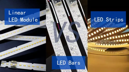
LED pitch, lens beam angle, and mounting height interact to determine whether a modular linear led lighting run reads as a smooth light plane or a dotted sequence. Too wide a pitch with too narrow a lens produces visible hot spots between LEDs. Custom optical design eliminates the bright-spot artifacts common when replacing fluorescent tubes with direct-fit led strip solutions not optically re-engineered for the cavity geometry.
How long does custom development take?
Higntek’s standard custom cycle is 15 days from confirmed brief to production-ready sign-off. That covers requirements analysis, PCB layout, prototype assembly on Samsung SMT equipment, AOI and X-ray verification, and Tj validation. The 15-day cycle is achievable because 25 SMT machines running in parallel eliminate the bottlenecks that extend timelines at lower-capacity facilities — a factor lighting designers working to fixed handover dates need to verify before committing to a supplier.
What testing ensures product reliability?
100% AOI and X-ray inspection on every production batch — not sampled lots — is the standard that separates manufacturing discipline from marketing claims. AOI catches solder bridges, tombstoned components, and polarity reversals at sub-0.1 mm resolution post-reflow. X-ray verifies solder joint voiding and via fill integrity in SMT packages AOI cannot reach. Every led linear module that ships has been inspected at the joint level, not assumed conformant because the batch electrical test passed.
Planning a Linear LED Module Project?
Whether you’re selecting a standard module, evaluating custom development options, comparing manufacturers, or estimating project costs, our engineering team can help you identify the most practical solution based on your performance goals, installation requirements, and budget.