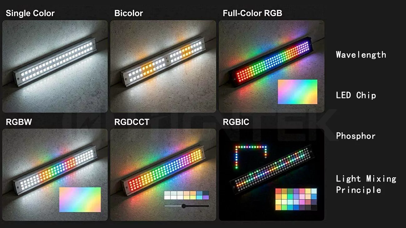
In practice, we do not judge LED module colour options by the color name alone. Red, green, blue, warm white, cool white, RGBW and tunable white may look like simple choices on a product list, but the real result comes from wavelength selection, LED chip structure, phosphor conversion, optical mixing, drive current and heat control. Once the module is placed inside a cabinet light, shelf lighting system, office luminaire or outdoor fixture, those details decide whether the color looks clean, stable and repeatable.
This is where many discussions about LED module color functionality become too shallow. Even when two white LED modules are both marked 3000K, their visible white point can still differ if SDCM, Duv, phosphor binning and thermal behavior are not controlled together. One module may look slightly yellow, pink or green, while another looks cleaner under the same diffuser and housing condition. An RGB module can create vivid color effects, but poor LED spacing or diffuser distance may leave red, green and blue edges near the lens. A tunable white module may shift smoothly from warm to cool on a datasheet, while the middle CCT range looks uneven because the warm-white and cool-white channels were not balanced carefully enough.
In LED module development, we usually treat color as a system rather than a single specification. Phosphor-converted white LEDs remain a common route for white light. RGB and RGBW modules depend more on additive color mixing. CRI helps us judge how naturally a white light source renders object colors, but it does not fully explain saturated RGB effects, color uniformity near a diffuser, or color shift after long operation. CCT, SDCM, wavelength binning, spectrum, optical layout and junction temperature all need to be read together.
That is also why custom LED module design should connect color requirements with component selection, PCB layout, optical structure, thermal management, SMT assembly and production testing. For an engineering-driven manufacturer such as Higntek, the value is not only offering different LED module colour options. The more practical work is making those color functions stable from sample development to mass production, so the final lighting product performs the way the project actually needs.
How Do LED Modules Produce Different Colors?
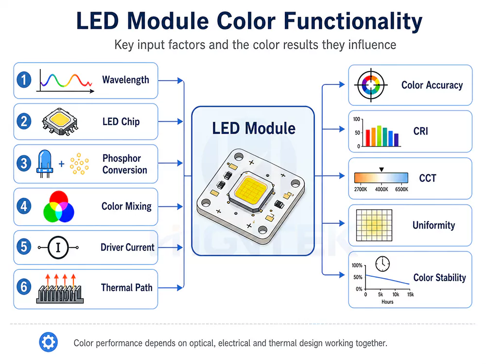
LED modules produce different colors through wavelength selection, LED chip, phosphor conversion and color mixing. We should not treat “red,” “warm white,” “RGBW” or “tunable white” as simple color names, because each option uses a different way to create and control light. Once the module goes into a cabinet light, shelf display, linear fixture or outdoor housing, the final color depends on the LED source, PCB layout, optics, drive current and heat path working together.
Wavelength.
Wavelength is the first thing we check. Visible light is usually discussed within roughly the 380 to 750 nm range, but LED module selection should focus more on peak wavelength than on the broad visible spectrum. In many LED applications, blue LEDs often sit around 460-490 nm, green LEDs around 520-550 nm, amber LEDs around 585-595 nm, and red LEDs around 620-645 nm. These ranges are not fixed color boundaries, but they help explain why the same color name can produce different visual results. For single-color LED modules, a red LED near 625 nm may look closer to orange-red, while a red LED closer to 640 nm can appear deeper and more saturated. That difference matters in signage, brand lighting, indicator modules and architectural accents, where the project needs a specific visual tone rather than a generic red, green or blue.
LED Chip.
The LED chip is the second factor. In a monochrome LED module, the chip itself is the color source, so wavelength bin, luminous intensity bin, forward current and thermal behavior all affect the result. In the RGB LED modules, red, green and blue emitters may be separate LEDs on the PCB or separate dies inside one RGB package. Each color works as an independently driven channel, connected through its own current path in the package and PCB layout. The driver circuit supplies current to the selected channels and adjusts their output ratio to create the target color, while the controller sends the color or dimming command.
In this sense, the color does not come from software alone. The PCB routing, solder pad design, driver-channel matching, channel current, LED placement, copper layout and local heat distribution can all change how clean the mixed color looks. This is why an RGB module can receive the correct signal and still show uneven color when the electrical layout or thermal layout is weak.
Phosphor.
Phosphor is the third factor, especially for white LED modules. Most white LED modules use phosphor-converted LEDs rather than a naturally white LED die. In a common structure, a blue LED die excites phosphor material, and the converted yellow, green and red components combine with the remaining blue light to create white light. Some designs may use near-ultraviolet excitation, but blue-pumped phosphor white remains the more familiar route in many lighting modules.
The phosphor recipe affects CCT, CRI, efficacy and visual comfort. A high-CRI white module usually needs more red-spectrum content, which can improve color rendering but may also influence efficiency and heat performance. That is why two 3000K modules may not make skin tones, packaging or wood surfaces look the same.
Color Mixing.
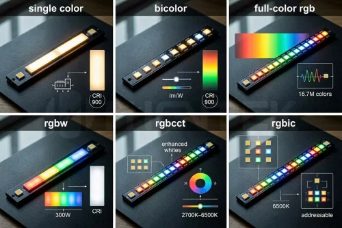
Color mixing is the fourth factor. RGB, RGBW and tunable white modules use several channels instead of asking one emitter to do all the work. RGB modules rely on additive color mixing, where red, green and blue light are blended in different ratios. RGBW modules add a white channel, which usually gives a cleaner and more practical white point than RGB-only white for lighting use. Tunable white modules mix warm-white and cool-white LEDs to create intermediate CCTs.
A common design may combine a warm-white channel around 2700K with a cool-white channel around 5000K to 6500K, but the middle range still needs careful calibration because the blackbody curve is not a straight line. In sample review, we usually check several CCT points, such as 2700K, 3000K, 4000K, 5000K and 6500K, instead of judging the tuning path only by its two endpoints.
For real product review, these four factors usually matter most:
| Factor | Main impact on LED module color functionality | Where it matters most |
|---|---|---|
| Wavelength | Decides the actual hue of single-color and RGB channels. A “red” LED with a deeper peak wavelength will not look the same as an orange-red LED. | Monochrome modules, RGB modules, signage, brand lighting, indicator lighting |
| LED chip | Sets the original emission, output level, wavelength bin and thermal behavior before optics or phosphor work. | Single-color modules, RGB modules, high-output custom LED modules |
| Phosphor | Converts blue or near-UV light into broader-spectrum white light. It affects CCT, CRI, efficacy and whether white light looks clean or dull. | Warm white, cool white, high-CRI white, tunable white modules |
| Color mixing | Blends multiple channels to create intermediate colors or adjustable white. Poor mixing can cause color edges, patchy light or pink/green white points. | RGB, RGBW, tunable white, dynamic color modules |
This is where many product tables become misleading. A module listed as RGBW or tunable white does not automatically mean the color transition is smooth, the white point is clean or the batch color is consistent. A compact shelf-lighting module with LEDs placed too close to a shallow diffuser may show color dots or colored edges. A tunable white board may look fine at 2700K and 6500K, then drift slightly pink or green in the middle range because the warm-white and cool-white channels were not balanced around the actual optical structure.
In custom LED module work, we normally connect the color target with LED chip selection, wavelength bins, phosphor-based white options, PCB layout, current design, diffuser distance and heat path. This is where Higntek’s engineering role becomes practical. Custom LED module work is not simply placing standard LEDs on a PCB. We help customers develop the LED module solution around LED selection, LED PCBA design, optical structure, thermal management, SMT assembly, testing and production consistency for the final lighting application.
How Does Color Mixing Accuracy Affect LED Module Performance?
Color mixing accuracy affects LED module performance by controlling color shift, color uniformity and the final viewing experience. A module can pass a basic power-on test and still fail visually when the mixed light shows colored shadows, patchy white areas, CCT differences between modules or visible color edges near a diffuser. In real projects, poor mixing usually appears in three places first.
- Near the diffuser, red, green and blue points may appear separately instead of blending into one smooth color.
- Along the edge of the light-emitting area, one channel may dominate because the LEDs are not positioned symmetrically.
- Across production batches, the same product code may look slightly different because wavelength bins, phosphor bins, SDCM control or drive current settings were not kept tight enough.
In one RGBW shelf-lighting project for a German cosmetics display supplier, the first sample looked clean during open-board testing. Once the customer installed a thin milky diffuser with an optical distance of about 8 mm, soft pastel colors showed a faint pink edge along one side of the shelf. The controller was not the main problem. Our review focused on RGBW channel spacing, diffuser distance and the white-channel ratio. In the revised sample, we increased the effective diffusion path from about 8 mm to about 12 mm, adjusted the LED arrangement and rebalanced the white-channel contribution. The visible pink edge was reduced in the final fixture, and the color looked more even on the actual shelf, not just on the workbench.
For white and tunable white modules, mixing accuracy is closely tied to SDCM and Duv. SDCM helps describe how tightly the visible color points are grouped, while Duv shows whether the white point sits above or below the blackbody curve. In side-by-side retail shelves, display cabinets and linear fixtures, a 3-step SDCM target is often a stronger choice than a wider 5-step selection when visible color consistency matters.
For dimmable and tunable white modules, we also check color-point stability during transitions, not only at one static setting. The review should cover the defined CCT checkpoints, full output, mid-level dimming and the project’s specified low-end dimming level. If the warm-white and cool-white channels are not calibrated well, the transition may show visible CCT jumps, greenish or pinkish tint or an uneven fade between brightness levels.
For RGB and RGBW modules, mixing accuracy also depends on control and thermal behavior. Red, green, blue and white channels do not respond to current and temperature in exactly the same way, so channel imbalance can quickly become visible color shift. During dimming, the same module may look accurate at full output but drift at lower levels if the channel current ratio, PWM behavior or thermal balance changes.
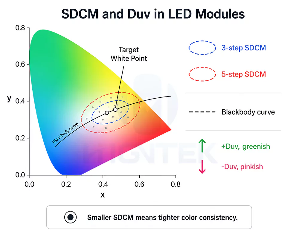
At the fixture level, this affects more than the color value itself, brand colors may miss their intended tone, pastel effects may look uneven, and a continuous shelf or linear fixture may no longer appear visually uniform. Stable constant-current driving, suitable PWM dimming, channel calibration, optical spacing and thermal design all help keep the mixed color closer to the intended visual result.
The practical correction is simple. LED module color functionality should be checked inside the final optical condition, not only on an exposed PCB. We need to evaluate the module with its intended lens, diffuser, housing distance, drive current and operating temperature. That gives a more honest view of whether the selected LED module colour options can support the real application.
What Is the Difference Between Additive Color Mixing and Phosphor Conversion in LED Modules?
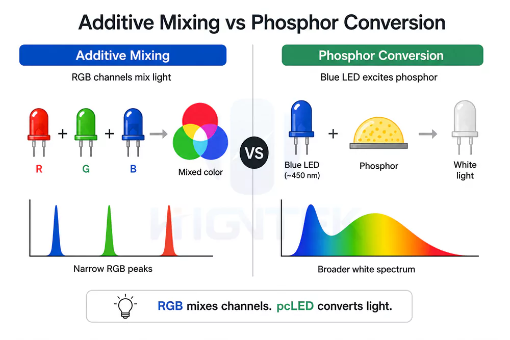
Additive color mixing produces color by mixing multiple independent monochromatic light sources (e.g., red, green, and blue) from LED channels, while phosphor conversion utilizes phosphor materials to convert part of the original light from the LED chip, thereby producing a broader spectrum of light. For LED module colour options, this difference is not academic. It decides whether a module is better suited for saturated color effects, practical white lighting, tunable white control or a hybrid RGBW design.
We usually explain it in a simple way. Additive color mixing is channel-based. Phosphor conversion is material-based. One depends on how red, green, blue and sometimes white or amber channels are balanced by current and control logic. The other depends on how a blue or near-UV LED die interacts with phosphor to create a broader spectrum. Both methods can support LED module color functionality, but they are not solving the same problem.
Additive Color Mixing.
Additive color mixing is the principle behind RGB and many RGBW LED modules. Red, green and blue LEDs emit their own wavelengths, then the eye blends those outputs into a perceived color. When red and green are on together, we see yellow. When red, green and blue are balanced, the result can look white. When each channel is dimmed separately through PWM or constant-current control, the module can create many intermediate colors.
That flexibility is useful, but RGB white is not the same as good illumination white. RGB white is built from narrower spectral peaks, so it may look white to the eye while still missing parts of the spectrum that objects need to reflect naturally. A white shirt, cosmetic label, wooden shelf or skin tone may look flat, gray or slightly unnatural under RGB-only white. This is why RGBW modules add a dedicated white channel. The RGB channels handle saturated color effects, while the white channel gives a cleaner and more practical white point for daily lighting.
Phosphor Conversion.
Phosphor conversion, often discussed as the phosphor-converted LED or pcLED technology, works differently. In many white LED modules, a blue LED die excites phosphor material. The phosphor converts part of the blue light into longer wavelengths, and the combined output appears white to the eye. Some designs may use near-UV excitation, but blue-pumped phosphor white is still the more familiar route in many lighting modules. Compared with RGB-only white, phosphor-converted white usually gives a broader spectrum, which is why it is widely used in office lighting, retail shelves, cabinet lighting, linear fixtures and other applications where object appearance matters.
The phosphor system controls much more than the white color name. It affects CCT, CRI, red content, efficacy and color stability. A warm-white module around 2700K needs a different spectral balance from a cool-white module around 5000K or 6500K. A high-CRI module usually needs stronger red-spectrum content, especially when the lighting is used for cosmetics, food, fabric, wood, skin tone or premium packaging. That extra red content can improve visual quality, but it may also reduce efficacy or make thermal control more demanding. In our LED module solution development, we normally treat this as a trade-off to manage, not as a simple “higher CRI is always better”.
For the custom LED module design, the choice is rarely additive mixing or phosphor conversion alone. Many useful products combine both. RGBW modules use additive mixing for color effects and a phosphor-converted white channel for more reliable white light. Tunable white modules mix two or more phosphor-converted white channels, usually warm white and cool white. Some color-tunable systems add amber, lime, mint or red-enhanced channels to improve color rendering, fill spectrum gaps or reach a more specific white point.
In one hospitality display project we worked on, the shelf-edge lighting needed to shift between brand colors in the evening and a clean daily white mode around 3000K to 3500K. The RGB-only samples handled the brand colors well, but the daytime white made cream-colored packaging look slightly gray. The issue was not that RGB was wrong. It was just the wrong method for that part of the visual task. We moved the design toward RGBW, kept RGB for accent scenes and used a phosphor-converted white channel with a CRI 90+ target for daily white lighting. The module kept its color flexibility, while the white mode became more useful in the actual display.
Here is the quick comparison we normally use when reviewing LED module colour options for a real product.
| Comparison Point | Additive Color Mixing | Phosphor Conversion |
|---|---|---|
| Principle | Blends light from separate LED channels. Red, green and blue are the basic channels, and white, amber or other colors may be added. | Converts part of a blue or near-UV LED’s emission into longer wavelengths through phosphor material. |
| Light source | Multiple monochromatic LEDs or several separately controlled color channels. | A blue or near-UV LED die combined with phosphor material. |
| Main components | RGB LEDs, RGBW LEDs, driver channels, control system, PCB layout and optical mixing structure. | LED die, phosphor layer or remote phosphor, package structure, PCB design and thermal path. |
| Spectral characteristics | Narrower spectral peaks. Strong for saturated colors, but RGB-only white can have spectrum gaps. | Broader white spectrum. The exact spectrum depends on phosphor recipe, CCT and CRI target. |
| Typical applications | RGB modules, RGBW modules, dynamic color lighting, signage, accent lighting and architectural color effects. | White LED modules, high-CRI lighting, tunable white modules, office lighting, retail lighting and cabinet lighting. |
| Main advantages | Flexible color control, saturated effects, dynamic scenes and easier digital adjustment. | More practical white light, better object color rendering potential and simpler white-channel control. |
| Main limitations | RGB-only white may look unnatural and may shift with dimming, temperature or channel imbalance. | Less dynamic by itself, and high-CRI or warm-white designs need careful efficacy and thermal management. |
For the LED module color functionality, this comparison helps correct a common misunderstanding. RGB is not automatically better because it offers more colors. Phosphor white is not automatically better because it gives more natural white. The right choice depends on the visual task. A brand accent light may need saturated color and smooth control. A retail shelf module may need CRI, CCT consistency and clean white. A hospitality or display module may need both, which is where RGBW or hybrid channel design becomes more practical.
For a custom LED module manufacturer like our Higntek, this choice should be made during the solution-development stage, not after the module layout is already fixed. When customers need both color effects and usable white light, we help define which channels create the visual effect, which phosphor-converted white LED package carries the white mode, and how the RGB or RGBW channel arrangement, PCB electrical layout, driver current stability and optical mixing distance support the intended color result. Once the sample direction is confirmed, the design can move into SMT production, testing and batch consistency control.
How Does CRI Affect Different LED Color Function Modules?
CRI affects LED color function modules by showing how naturally a white or near-white light source renders object colors, but it does not mean the same thing for every module type. For phosphor-converted white modules, CRI is a core quality indicator. For tunable white modules, we need to check CRI across the full CCT range. For RGB, RGBW and single-color modules, CRI only tells part of the story, and sometimes it is not the right metric at all.
CRI is useful for judging how naturally a white or near-white LED module renders object colors, but it should not be treated as a universal score for every color function. A buyer may see CRI 80, CRI 90 or CRI 95 and assume the highest number always means the best LED module color functionality. In practice, CRI mainly applies to phosphor-converted white modules, RGBW white channels and tunable white modules. It helps us judge whether skin tone, wood, food, cosmetics, fabric or packaging looks natural under white light. It does not tell us whether an RGB module can create a deeper blue, whether a brand red sits on target, or whether a narrow-band amber signal module is performing correctly.
For phosphor-converted white LED modules, CRI 80 is often used as a practical baseline for general lighting, while CRI 90 or higher is usually preferred for retail lighting, hospitality lighting, beauty displays, jewelry counters, food shelves and premium residential fixtures. Even then, CRI should not be read alone. Two modules can both be marked CRI 90 and still look different on real products because their R9 value, spectrum shape, CCT, SDCM and Duv may differ. That is why we review CRI together with R9, CCT, SDCM, Duv and the actual application surface before deciding whether the white light is suitable for the module’s color function.
- For tunable white LED modules, CRI should be checked according to the channel structure, not only by the product name. In a bi-color or CCT tunable white module, the warm-white and cool-white channels carry the main white-light output, so CRI needs to be reviewed at both endpoints and at key mixed CCT points. In an RGBCCT or RGB+CCT module, the RGB channels create saturated color effects, while the warm-white and cool-white channels carry the practical white mode. For this structure, CRI mainly belongs to the CCT white channels and near-white mixed settings, not to saturated RGB scenes. Even if the endpoints look acceptable, CRI, R9, Duv and visual comfort can still change across the tuning path.
- For RGB modules, CRI is often the wrong first question. Pure RGB color effects are judged more by wavelength, color gamut, mixing accuracy, dimming smoothness and visual uniformity. When an RGB module creates saturated red, green, blue, purple or cyan, the goal is not natural object rendering. The goal is color effect. CRI becomes relevant only when RGB is mixed toward white or near-white illumination. Even then, RGB-only white can look white to the eye while leaving gaps in the spectrum, so skin, packaging, fabric or wood may not look natural.
- For RGBW modules, CRI mainly depends on the white channel when the module is used for practical illumination. The RGB channels handle saturated color scenes, while the white channel should be evaluated for visibility, product display and daily lighting. If the white channel is CRI 90 and the optics are well matched, the module can keep creative color functionality without losing basic lighting quality.
- For single-color LED modules, CRI usually has limited meaning. A red indicator module, blue accent module or amber signal module is designed to produce a specific narrow color, not to render all object colors naturally. In these cases, peak wavelength, wavelength bin, brightness, viewing angle, optical uniformity and long-term color stability matter more. Calling the CRI low does not automatically mean the module is poor. It may simply mean CRI is not the right tool for that color function.
- For special spectral modules, CRI can be secondary or irrelevant. Plant-growth lighting, inspection lighting, signal lighting and decorative narrow-band modules often aim for a specific spectral output. We need to check the target wavelength range, spectral power distribution, radiant or luminous output, thermal stability and operating environment. A module can have poor CRI and still perform correctly when its job is not natural color rendering.
We usually separate CRI evaluation by module type like this.
| LED color function module | How CRI should be used | What else we need to check |
|---|---|---|
| Phosphor-converted white module | Core indicator for object color rendering. CRI 80 may work for general lighting, while CRI 90+ is safer for color-sensitive spaces. | CCT, R9, spectrum shape, SDCM, Duv, efficacy and thermal stability |
| Tunable white module | Check CRI at several CCT points, not only warm and cool endpoints. | CCT tuning path, Duv shift, channel balance, dimming behavior and consistency between modules |
| RGB module | Not the main metric for saturated color effects. It matters only when RGB is mixed toward white. | Peak wavelength, color gamut, mixing accuracy, PWM dimming, diffuser distance and color uniformity |
| RGBW module | Mainly judged through the white channel when used for illumination. RGB handles color scenes. | White-channel CRI, RGB channel balance, optical mixing, control logic and thermal behavior |
| Single-color module | Usually limited value, because the module is designed for one narrow color. | Peak wavelength, bin tolerance, brightness, viewing angle and long-term color stability |
| Special spectral module | Often secondary or unsuitable when the module is designed for plant growth, signaling, inspection or decorative color. | Spectral target, output stability, wavelength range, power level and operating environment |
In one jewelry display module review, the project requirement first came to us as the high CRI RGB lighting, because the fixture needed warm display light and color scenes for seasonal campaigns. After sample review, the real requirement became clearer. The diamonds and metal surfaces needed a stable white mode around 3000K, with a CRI 90+ target and R9 review, while the RGB effect only needed clean accent color around the display edge. We moved the design direction toward an RGBW structure with a controlled white channel rather than asking RGB to create all white light. That gave the display a more reliable daily lighting mode and kept the color scenes for visual merchandising.
For custom LED module development, color stability should be handled from the beginning, not corrected only after aging problems appear. LED selection, phosphor system, PCB thermal design, drive current, diffuser material, adhesive compatibility and aging verification need to work together. For a custom LED module manufacturer like Higntek, this connects naturally with LED PCBA, optical design, thermal management, SMT assembly and reliability validation. The goal is not only to offer different LED module colour options, but to keep the selected color function stable inside the final lighting product.
What Causes Color Shift in LED Modules Over Time?
Color shift in LED modules usually comes from LED aging, heat stress electrical stress and material changes. In real lighting products, it may appear as warmer or cooler white light, a greenish or pinkish tint, weaker saturated colors, visible mismatch between old and new modules, or uneven color across the same light-emitting surface.
We should separate color shift from simple brightness loss. A module can still look bright enough but no longer look right. In a retail shelf, a small CCT or Duv shift may make white packaging look yellow beside a newer batch. In office lighting, several linear modules installed in one row may slowly stop matching each other. In RGB or RGBW lighting, one channel may lose output faster than the others, so the mixed color no longer lands where the controller expects it to land.
LED aging.
LED aging is the first cause. Over time, the LED chip’s output changes, and different colors do not always age at the same speed. In RGB modules, red, green and blue channels can lose output differently. A color recipe that looked balanced during sample testing may become warmer, cooler or less saturated after long operation. In white LED modules, the blue pump LED and phosphor layer work together, so aging can change both brightness and the white point.
Phosphor degradation is especially important for white LED modules. In phosphor-converted LEDs, the phosphor layer converts part of the blue or near-UV emission into longer wavelengths. When phosphor efficiency changes, the module’s CCT, CRI and Duv can move with it. A warm-white module may become slightly cooler if the longer-wavelength converted output weakens. In other cases, the white point may move toward yellow, green or pink depending on which part of the spectrum changes most.
Thermal Stress.
Temperature is often the strongest accelerator. Higher junction temperature speeds up degradation in the LED package, phosphor system, encapsulant and nearby optical materials. That is why color stability is closely tied to PCB design, copper area, aluminum or copper substrate selection, solder quality, housing structure and air path. A module may look stable on an open test bench, while the same module inside a sealed narrow fixture may run hotter and shift color faster.
Material aging.
Material aging is another common reason. Encapsulants, silicone, plastic lenses, reflectors and adhesives all sit close to heat and light. Over time, some materials can yellow, crack, absorb light or change how they transmit or reflect light. Chemical compatibility also matters. Certain volatile compounds from adhesives, sealants, paints, cleaning agents or nearby plastics can interact with LED package materials under heat and high photonic energy. In practice, this can turn a material issue into a color stability issue, especially in blue, royal blue and phosphor-converted white LEDs. Research on LED failure mechanisms also identifies VOC contamination as a cause of phosphor-layer discoloration in pc-LEDs.
Electrical Stress.
Electrical stress can also create color shift. Overdriving an LED may raise light output at first, but it also raises junction temperature and accelerates degradation. In tunable white or RGBW modules, unstable current balance can change the ratio between channels. The module may look correct at full power, then drift at low dimming levels because each channel responds differently to current, temperature and PWM control.
Production variation becomes visible over time as well. When the first batch and service batch use different wavelength bins, phosphor bins, diffuser materials or PCB thermal paths, the mismatch may look small during incoming inspection but obvious after installation. Therefore, to achieve accurate and consistent LED module color, we control it during mass production through LED grading, SDCM target values, optical verification, and aging tests, not just the color name on the Bill of Materials (BOM).
A practical way to read color shift is to look at what changed visually first. Here are some practical guidelines based on our more than ten years of experience for preliminary visual assessment.
| Visible problem | Likely technical cause | What we should check |
|---|---|---|
| White light becomes warmer or cooler | Phosphor change, blue LED aging, thermal stress or CCT bin mismatch | CCT drift, Duv, phosphor stability, junction temperature |
| White light looks greenish or pinkish | Duv shift, phosphor spectrum change, optical material aging or channel imbalance | Duv, SDCM, diffuser material, thermal path |
| RGB color no longer matches the original effect | Uneven aging of red, green and blue channels | Channel output, current balance, PWM setting, operating temperature |
| Old and new modules look different side by side | Batch variation, LED bin change or material change | LED bin records, SDCM range, supplier consistency, aging data |
| Light surface becomes patchy | Uneven heat distribution, material yellowing or local LED degradation | PCB layout, housing heat flow, lens and encapsulant condition |
| Color changes faster inside the final product than in sample testing | Final fixture traps more heat or uses incompatible nearby materials | Housing temperature, airflow, adhesive and sealant compatibility |
*This is for preliminary reference only; actual testing is still required.
In one outdoor linear module review for a façade lighting customer in Southeast Asia, the first engineering samples looked consistent after bench testing. After several months of high-temperature operation inside a narrow aluminum housing, part of the installed run began to look slightly warmer than the replacement modules. The issue was not a wrong CCT order. Our review pointed to two practical causes: the sealed end section was running about 8°C to 10°C hotter than the more open middle section, and the service-stock modules used a slightly different LED bin from the original batch. After improving heat transfer around the end section, tightening LED bin control and defining replacement stock by the same color bin group, the visible mismatch between the replaced section and the original run was reduced in side-by-side review.
For custom LED module development, we normally treat color stability as an engineering task from the beginning. We need to check LED selection, phosphor system, PCB thermal design, drive current, diffuser material, adhesive compatibility, operating temperature and aging verification together. For a custom LED module manufacturer like the Higntek, this fits naturally with its LED PCBA, optical design, thermal management, SMT assembly, reliability validation and full-cycle manufacturing work. The goal is not only to offer different LED module colour options, but to keep the selected color function stable inside the final lighting product.
Good LED module colour options are not decided by color names alone. The visible color output of an LED module is not simply determined by the LED chips themselves—it is the result of complex interactions between semiconductor materials, optical mixing, control systems, thermal conditions, and long-term reliability factors.
From our experience working with custom LED module projects, achieving consistent color performance is often more challenging than creating the color itself. A module may produce the correct color in initial testing, but maintaining color accuracy over thousands of operating hours requires careful control of LED bin selection, optical design, thermal management, and electrical stability.
At Higntek, we consider color performance as a complete system design challenge. Whether developing single-color, RGB, RGBW, RGBCCT, or other customized LED modules, our engineering team evaluates optical requirements, color consistency, control compatibility, and application conditions together to create reliable lighting solutions.
For lighting brands and manufacturers developing next-generation products, understanding LED module colour principles helps make better design decisions, reduce development risks, and achieve more consistent results in real-world applications.
How do thermal conditions affect LED color stability?
Thermal conditions affect LED color stability by changing LED output, wavelength behavior, phosphor performance and long-term material aging. When junction temperature rises, white LED modules may show CCT drift or Duv shift, while RGB modules may lose channel balance because red, green and blue LEDs do not respond to heat in exactly the same way.
In custom LED module development, we normally treat thermal management as part of color design, not only as a lifetime issue. Higntek’s work in PCB layout, LED PCBA, optical design and thermal management helps keep the selected LED module color functionality more stable inside the final lighting product.
What is the difference between color rendering and color changing?
Color rendering means how naturally a light source shows object colors, while color changing means how the module creates different light colors. CRI belongs mainly to color rendering, especially for white LED modules. RGB, RGBW and tunable white belong more to color changing or color control.
This distinction matters because a module can change into many colors and still render objects poorly in white mode. For retail, display and hospitality lighting, we usually check CRI, CCT, SDCM and white-channel quality instead of judging the module only by RGB effects.
Is a higher CRI always better for LED modules?
A higher CRI is useful for color-sensitive white lighting, but it is not always the only or best metric. CRI 90+ is often preferred over CRI 80 in color-sensitive spaces because object color matters more.
For RGB, single-color or special spectral modules, CRI may have limited meaning. We should also check wavelength, spectrum shape, R9, CCT, SDCM, Duv, efficacy and thermal stability before deciding whether the LED module colour options fit the application.
Can RGB LED modules replace white LED modules?
RGB LED modules can create white-looking light, but for practical illumination we usually prefer a phosphor-converted white channel or an RGBW structure. RGB white is made from narrow red, green and blue spectral peaks, so it may look white while making skin, packaging, fabric or wood appear unnatural.
That is why RGBW is often a better choice when one module needs both color effects and usable white light. The RGB channels handle atmosphere and brand color, while the white channel supports daily lighting and object visibility.
How should we evaluate LED module colour options before mass production?
We should evaluate LED module colour options under the final optical, electrical and thermal conditions, not only on an exposed PCB. The key checks include wavelength bin, CCT, CRI, R9, SDCM, Duv, diffuser distance, drive current, dimming behavior, operating temperature and aging performance.
For custom LED module projects, sample approval should also include batch consistency and replacement planning. A color that looks correct in the first sample still needs to remain stable after SMT production, fixture assembly and long-hour operation.
Create a Custom LED Module with Precise Color Performance
From RGB color mixing and tunable white systems to customized optical and electrical designs, Higntek supports complete LED module development from concept validation to mass production.