How Luminous Efficacy Determines LED Module Performance and Energy Savings

Luminous Efficacy Explained How to Improve LED Module Efficiency

A nominal 225 lm/W LED datasheet and the actual installed and operating luminaire are two different things. Luminous efficacy, the ratio of light output to power input, decides how much a project pays for every lumen it gets: it sets the electricity bill, the waste heat the housing has to absorb, and whether the fixture qualifies for efficiency certifications and utility rebates. Let’s delve into the physical definition and standard calculation of luminous efficacy. Visit our lab to see our methods for measuring LED luminous efficacy and the difference between lab values ​​and field performance. Higntek’s system engineering design for improving LED module luminous efficacy, and standards for selecting, customizing, and certifying high-efficiency LED modules.

What is Luminous Efficacy?

Luminous efficacy (symbol η, unit lm/W) is the ratio of the luminous flux a light source emits, measured in lumens, to the electrical power it consumes, measured in watts. It states how efficiently the source converts electrical energy into visible light: a module rated at 180 lm/W delivers 180 lumens for every watt it draws. Wattage alone says nothing about light delivered; it only measures power drawn, which is why two 50 W fixtures can perform very differently on the same ceiling.

  • It cuts operating costs by a calculable margin. Higher lm/W means fewer watts for the same lumens. A high-efficacy module at 200 lm/W produces the same light as a typical fluorescent lamp (about 80 lm/W) while consuming roughly 60% less energy, and the same light as a standard 130 lm/W LED module while using about 35% less power. Across a warehouse running hundreds of fixtures 4,000 hours a year, that gap is the difference between two very different utility budgets.
  • It shrinks the thermal budget. Every watt not converted to light becomes heat inside the housing. A higher-efficacy module generates less waste heat at equal output, so the luminaire can use a smaller, lighter, cheaper heat sink without compromising junction temperature or lifespan.
  • It gates access to premium markets. In North America, DLC SSL V5.1 sets Premium efficacy thresholds such as 135 lm/W for high-bay luminaires, and many utilities tie cash rebates to DLC-listed products. In the EU, the ErP regulation (EU) 2019/2020 ties energy labeling to efficacy performance. Modules that cannot document high efficacy are excluded from these projects before price is ever discussed.
What is Luminous Efficacy

The metric has a hard physical ceiling. Human photopic vision peaks at 555 nm (green), where the theoretical maximum is 683 lm/W; real white LEDs sit far below that limit because of heat, optical, and electrical losses. Some production LED chips currently reach 200 to 220 lm/W under laboratory conditions, and complete modules measure lower. For commercial buyers and contractors, this single number dictates waste heat, long-term utility costs, and project ROI.
After years of research and development, Higntek now offers advanced semiconductor solutions such as NCSP, PCT, PPA, and EMC, achieving an extreme luminous efficacy of 272 lm/w with low current and an ultra-high luminous efficacy of 265 lm/w with high current, covering a full range of applications from 2835 to 5050. Through systematic thermal management and optical design engineering solutions, the luminous efficacy loss of our LED modules can be controlled to within 10%.

Luminous efficacy vs luminous efficiency.

Luminous efficacy measures how well a light source converts electrical power into visible light, expressed in lumens per watt. It is the working metric of commercial lighting: datasheets quote it, rebate programs threshold it, and energy models are built on it.
Luminous efficiency is a different, theoretical quantity. It measures how much of the input power becomes visible radiation relative to a defined maximum, expressed as a percentage, and it belongs to academic physics and lighting research rather than commercial specification.
As commercial LED module manufacturers, the Higntek engineering team specifies and tests against luminous efficacy, because that is the figure that decides a client’s energy bill. Luminous efficiency stays in the lab literature. The table below summarizes the distinction for quick reference.

MetricLuminous EfficacyLuminous Efficiency
DefinitionRatio of luminous flux to input powerRatio of visible output to a defined theoretical maximum
Unitlm/W (lumens per watt)% (percentage, dimensionless)
Engineering useMeasuring energy-to-light ROIAnalyzing spectral conversion in research
Max limitAbout 683 lm/W (monochromatic green, 555 nm)100%
Commercial relevanceCritical: directly sets energy bills and rebate eligibilitySecondary: theoretical benchmark

How to Calculate Luminous Efficacy?

Datasheet efficacy figures deserve verification before any comparison, because the data parameters provided for customized LED modules vary depending on their engineering design schemes. The calculation itself uses one standard formula:

Luminous efficacy (lm/W) = Luminous flux (lm) / Power consumed (W)
η = Φ / P

Applied to a real module: if a LED module emits 6,500 lumens while drawing 36 watts at the wall, it operates at 6,500 / 36, or about 180 lm/W. If a second LED module needs 50 watts for the same 6,500 lumens, it delivers only 130 lm/W, and the difference shows up on the electricity meter every hour the installation runs.
Two conditions decide whether a quoted number is meaningful. First, check the measurement level: chip-level ratings are captured at a 25°C junction temperature and low drive current, so module-level efficacy under real operating conditions always sits lower, typically by 10 to 20%. Second, check the thermal state: a credible figure is measured at thermal equilibrium under steady-state operation, not in the first seconds after switch-on. A claimed 225 lm/W is real engineering only when both conditions are stated.

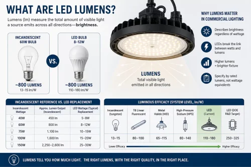
Benchmarks turn an abstract number into a decision. Understanding the luminous efficacy range of standard LED lighting modules (120-210 lm/W), or the peak value of fluorescent tubes approaching 100 lm/W, allows lighting engineering and procurement teams to quantify energy-saving effects, estimate the payback period, and confirm eligibility for subsidies before selecting suppliers. Here is the comparison table based on the IESNA Lighting Handbook, the U.S. Department of Energy (DOE), and mainstream industry standards for solid-state lighting.

Light Source TypeEfficacy Range (lm/W)Typical ApplicationsTechnical Characteristics
Incandescent Bulbs12.6 –52Decorative, vintage residential90% of energy is wasted as heat rather than light.
Halogen Lamps16 – 25Spotlights, automotive headlampsSlightly more efficient than incandescent, but still a major heat generator.
Fluorescent Lamps50 – 100Offices, supermarketsRelies on mercury vapor discharge; efficient, but carries environmental risks.
Arc / HID Lamps60 – 120Stadiums, street lighting; searchlightsIncludes Metal Halide (MH) and High-Pressure Sodium (HPS); slow warm-up times.
Standard LED Module100 – 150General commercial lightingThe most common cost-effective choice in today’s market.
High-Efficacy LED160 – 265+Industrial High-Bays, Higntek projectsUses top-tier chip binning and precision thermal engineering.
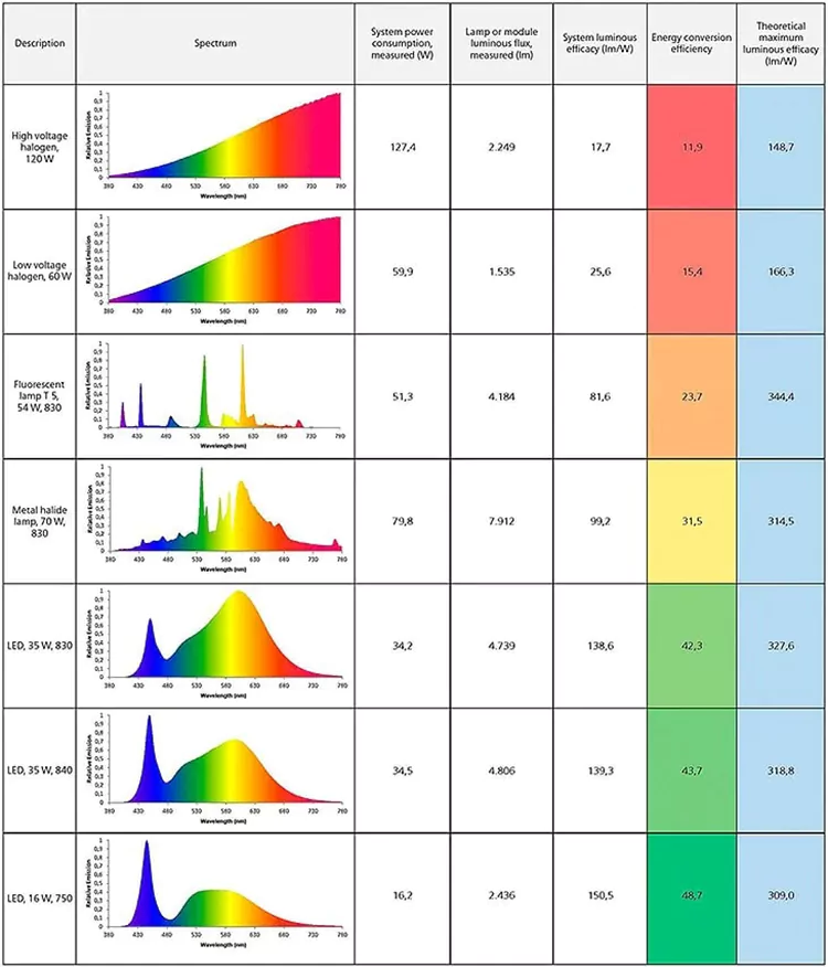
DIAL luminous efficacy is dependent on the spectrum

The above chart, from DIAL, reveals a pattern more significant than any single data point: LED performance has far surpassed all traditional technologies, and within LEDs, the gap between standard and high-efficiency modules is the key to project economics. That spread, not the nominal wattage, is what a procurement team should be pricing.

According to CIE and IES standards, luminous flux is measured with two laboratory methods: the integrating sphere method and the goniophotometric method. The integrating sphere gives a fast relative measurement of total flux and colorimetric data; the goniophotometer gives an absolute measurement by mapping intensity distribution angle by angle.
Because the two principles differ, their flux values for the same product can differ as well, and each method fits different products: spheres suit single LEDs and small, near-omnidirectional modules, while goniophotometers handle large or directional luminaires and produce the .ies and .ldt files lighting designers need. For B2B buyers evaluating a manufacturer, understanding the test setup behind datasheet numbers is the first defense against inflated performance claims.
In compliance testing and optical auditing, tier-one manufacturers rely on two distinct testing architectures. Each serves a specific role in the quality control and simulation pipeline.

  • Integrating Spheres: The sphere is the primary quality gate for verifying raw LED modules before they are integrated into luminaire housings.
  • System principle: The setup uses an enclosed hollow sphere coated internally with a highly reflective, non-selective diffuse material such as barium sulfate or PTFE. The LED source sits at the center, the coating scatters light uniformly across the interior, and a baffled spectroradiometer port samples the integrated light, capturing total luminous flux in a single fast measurement.
  • Performance metrics: This is the industry-standard process for verifying raw efficacy (lm/W), Correlated Color Temperature (CCT), and Color Rendering Index (CRI).

Compliance Benchmarks & Data:

  • North America (DLC 5.1 Premium): tested in a controlled environment of 25°C ± 1.2°C, modules must meet efficacy thresholds of 135 lm/W for high-bay and industrial luminaires, 130 lm/W for linear ambient and commercial luminaires, and 120 lm/W for outdoor and general area luminaires.
  • European Union (CE/Ecodesign): color consistency must hold within SDCM ≤ 4 steps to comply with EU energy-labeling rules.
  • Compliance protocols: testing follows IES LM-79-19 (Clause 9.2) and CIE S 025.

Goniophotometry.

The goniophotometer translates module performance into delivery-ready lighting design data. Its core value is precise distribution data for the luminaire, and different regions impose specific requirements on that data. Inside a light-absorbent darkroom, a mechanized rig rotates the light source (or detector) to capture intensity across angular coordinates, compiling absolute photometric files in .ies or .ldt format.

  • North America (DLC/IES): DLC requires .ies files from an ISO/IEC 17025 accredited laboratory, and IES standards require full-space intensity capture so that lumen distribution calculations hold across architectural scenarios. Measurements stay at 25°C ± 1.2°C for inter-laboratory comparability.
  • European Union (CE/Ecodesign): Regulation (EU) 2019/2020 prioritizes Useful Luminous Flux, calculated within defined cones (typically 90° or 120°), and raw data must be validated against CIE 121:1996 or ISO/CIE 19476 to support CE declarations.
  • Global specifications: IES LM-79-19 (Clause 9.3) is the universally accepted standard for goniophotometric accuracy. North American applications use the data mainly for DLC classification; EU applications focus on Ecodesign energy-rating verification.

The luminous efficacy in LED datasheets is almost always measured under controlled laboratory conditions at the nominal junction temperature. Once a fixture runs continuously in an industrial facility or outdoors, compounding thermal, optical, and electrical penalties degrade that theoretical figure:

Thermal degradation and droop. Continuous operation generates heat, and luminous efficacy falls as junction temperature rises. If the thermal path is insufficient, the junction can stabilize at 85°C or higher, cutting light output by roughly 2 to 8 %. In severe cases, sustained overheating goes beyond light loss: it accelerates lumen depreciation, shortens service life, and becomes a safety risk.
Secondary optics attenuation. Lenses and diffusers shape the beam but absorb photons, typically 5 to 15% of total output. When developing and designing LED lighting modules, we balance luminous efficacy and uniformity according to customer needs.
Driver efficiency and parasitic losses. Standard drivers operate at 88 to 92% efficiency, so another 5 to 15% of input power is lost as heat before it reaches the chips.

Real-world delivered efficacy = Lab efficacy – driver loss – optical attenuation – thermal droop.

Some efficacy loss between the laboratory and the field is inevitable; no module escapes driver losses, optical attenuation, and thermal droop entirely. What engineering can do is keep every one of those losses as small as physics allows, and that is never a single-component job. It requires a systematic design of the entire LED module’s energy conversion process: LED chip selection and grading, optical performance matching, and driver efficiency.
That is the basis on which Higntek develops high-efficacy modules, and it is why the efficacy figures worth trusting are the ones validated after steady-state thermal stabilization, not flash-tested laboratory peaks.

How to Improve The Luminous Efficacy of LED Modules?

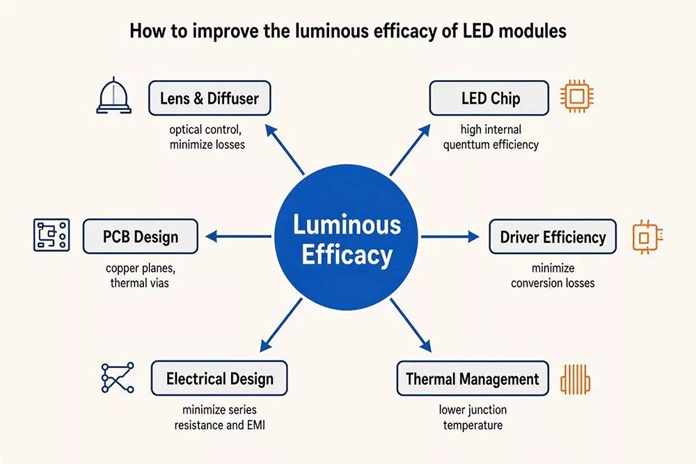
Improving the luminous efficacy of an LED module means cutting every loss between the wall socket and the emitted photon. In practice, our engineering teams work six levers: premium LED chips driven inside their efficacy sweet spot, high-efficiency drivers, system-level thermal management, high-transmittance optics, low-loss electrical design, and a PCB layout engineered for heat flow and current symmetry.
How to improve the luminous efficacy of LED modules

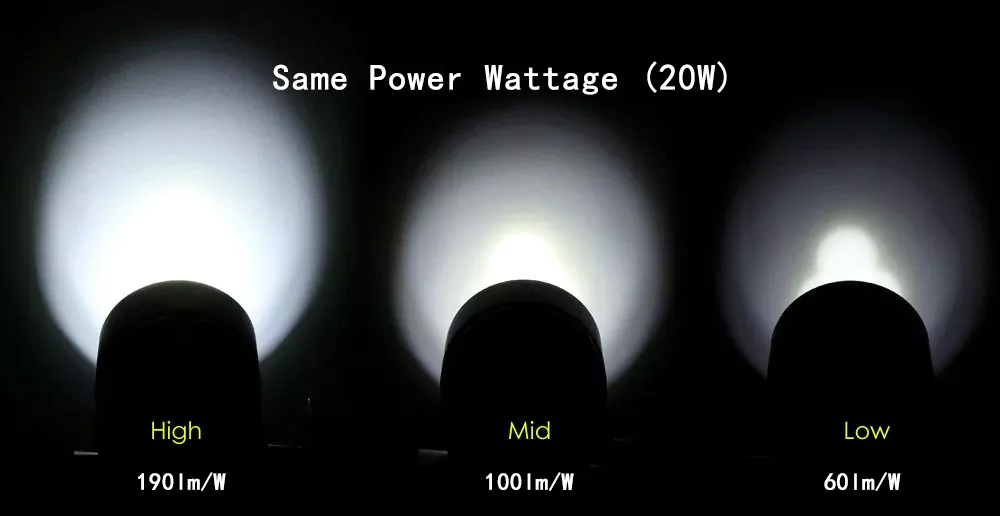
At equal input power, the high-efficacy module delivers about 73% more light (225 vs 130 lm/W). In a real layout, that is the difference between a dim floor and full design lux, or the opportunity to specify fewer fixtures for the same result.
Flipped the other way, the high-efficacy module needs roughly 42% less input power for the same light output (about 69 W instead of 120 W), and waste heat falls in proportion. A standard module may force a 2 kg heat sink to keep junction temperature safe; the high-efficacy design allows a much slimmer housing. On large projects, the savings in aluminum, shipping weight, and installation labor can exceed the price premium of the better modules.
Using inefficient LED lights wastes energy, drives up operating costs, and degrades performance over time. To maximize the luminous efficacy (lm/W) of an LED module, the whole energy conversion chain has to be optimized as one system rather than as isolated components. By controlling the variables below, a module design can deliver measurably lower energy costs and a longer operational lifespan.

Choose High-Efficiency LED Chips.

The core of any LED module is the chip, a semiconductor structure where electrons and holes recombine to release photons. Chip architectures and binning quality vary widely in conversion efficiency, and higher luminous efficacy at chip level translates directly into lower system power. Currently, the highest mainstream level of high-quality commercially available LED chips in daily mass production is 180–220 lm/W. Our independently developed top-tier LED light source achieves a light source-level luminous efficiency of 280 lm/W, while the module-level luminous efficiency based on these LED chips (optimized for thermal management and optical loss) can reach 265 lm/W—we confidently claim this is the upper limit of current high-efficiency design.
Two conditions make that number meaningful. Chip-level ratings are measured at a 25 °C junction temperature and low drive current, so module-level efficacy under real operating conditions will always sit lower. And binning discipline matters as much as the peak figure: a supplier who can lock a specific flux and color bin across batches protects both efficacy and visual consistency in volume production.

Getting the most from those chips is not a numbers game. Adding LEDs to reach an efficacy target raises component count, power density, and thermal-management complexity. High-efficacy module design usually goes the other way: use the fewest high-efficacy chips that still meet the project’s brightness and uniformity requirements, and drive each one inside its efficacy sweet spot — the current range where lm/W peaks before efficiency droop sets in. Chip count follows the optical requirement; it is not the efficacy strategy.

If a project requires higher efficiency and prioritizes cost-effectiveness, we will independently develop high-efficiency LED light sources through specially designed packaging architectures, materials, and processes—currently, our source-level EP reaches a maximum of 280 lm/W, and our module-level EP reaches a maximum of 265 lm/W. Please browse our  LED Chip Resources to find chip specifications and architectures that match your target EP.

Use Higher Driver Efficiency.

The LED driver regulates voltage and current for the whole system, and driver sizing needs a precise thermal and electrical balance:

  • Under-driving risks: A driver with insufficient capacity cannot supply the matrix properly. System efficacy drops, and the wasted electrical energy turns into heat.
  • Over-driving risks: A driver running at excessive power overloads the LEDs, causing overheating, faster lumen depreciation, and premature component failure.

Selecting a high-efficiency driver is not optional for high-power fixtures. A premium driver rated above 90% efficiency is ideal: at equal light output, a 90%-efficient driver wastes about 11% of input power as heat, while an 80%-efficient unit wastes 25%. That is nearly two and a half times the parasitic loss, and the thermal design has to absorb all of it.

The choice of driver depends on the customer’s lighting design, and our responsibility is to ensure the module performs at its best. Higntek’s electrical engineers design the module’s electrical architecture around the customer’s driver requirements — matching the volt-ampere (V-I) characteristics of each LED matrix to the driver’s output window, and adapting the module to the specified dimming protocol, whether DALI, 0-10V, Push Dim, or DMX512. This matching matters more than most buyers expect: even two LED part numbers sharing the same 5050 footprint can peak at very different voltage and power conditions, so the electrical design is what lets the chips run at their highest sustained efficacy under the coolest, most stable operating conditions. Contact us here to align the module design with your driver and dimming plan.

Thermal Management.

Excessive heat is the primary enemy of efficacy; it accelerates lumen degradation and severely shortens the operating life of the fixture. LED thermal droop describes the physical phenomenon where luminous efficacy falls dynamically as junction temperature rises. As a working rule, white LED output drops roughly 0.1 to 0.3% per °C of junction temperature increase, so a module rated at 25 °C can lose 5 to 10% of its light output once the junction stabilizes at 85 °C inside a sealed luminaire. Severe thermal failure goes further, threatening both operational safety and service life.
Thermal management is a complete engineering discipline, not a single heat-dissipation path. Heat generated at the LED junction must travel through the package, solder joints, PCB, thermal interface materials, and the heatsink or housing before it reaches ambient air, and every interface adds thermal resistance — the weakest link sets the steady-state junction temperature. That is why thermal design should be planned concurrently with electrical, optical, and mechanical design, not checked after the mechanical work is done.
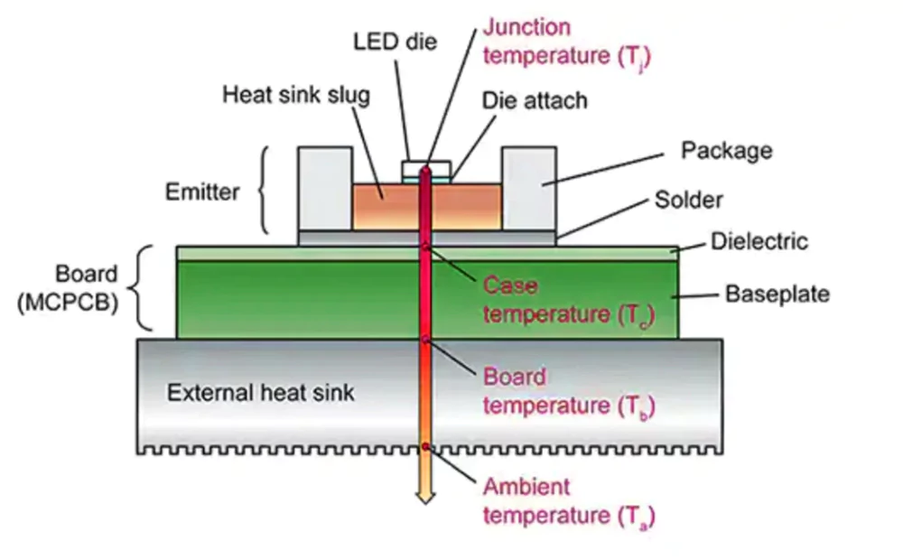
What is junction temperature in LEDs

At Higntek, thermal evaluation runs through the entire module development cycle — LED selection, PCB material(1 to 8 W/m·K MCPCB) and layout, thermal interface materials, driver and system thermal integration, and heatsink matching — validated by thermal simulation and steady-state testing before mass production. See how our thermal management engineering works in practice.

Choose High-Transmittance Optics.

Standard and low-quality optical components are prone to severe light trapping, in bad cases absorbing 15% to 20% of a luminaire’s total output. To minimize these losses, high-end industrial lighting avoids inferior plastics in favor of optical-grade PMMA (acrylic) or premium PC (polycarbonate).
Optical-grade PMMA transmits 92 to 93% of visible light, verifiable via the ASTM D1003 haze and transmittance standard; clear polycarbonate typically reaches 88 to 90%. For more demanding applications, an anti-reflective (AR) coating can push transmission past 95%.

When it comes to diffusers, the engineering focus shifts to balancing light transmission with appearance. Diffusion is always a trade-off: stronger diffusion improves uniformity and visual comfort but scatters or absorbs part of the output, typically costing 5 to 13% of luminous flux. A diffuser with 85% transmittance and one with 95% transmittance deliver very different combinations of light loss and uniformity, so the choice has to follow the project’s priority: visual comfort, brightness, or energy efficiency rather than defaulting to the strongest diffusion material. Done well, luminaires achieve a clean, refined aesthetic without boosting power consumption or relying on higher-power LEDs.
Higntek treats optical design as a system engineering stage: LED selection, custom lens and beam-angle optimization from 15° to 120°, diffuser and glare-control engineering, and optical simulation with photometric validation before mass production — all aimed at keeping optical loss low while hitting the application’s distribution and uniformity targets. See our optical design engineering capability.

Optimize electrical design.

Selecting the right LED chip and driver is not enough on its own. If the circuit design is poor, electrical energy is wasted as heat before it reaches the chip. Sound electrical design ensures the LEDs receive a stable power supply and operate at peak efficiency.
To maximize luminous efficacy, the electrical design should focus on precise current control and the minimization of line losses. An effective voltage regulation mechanism prevents power loss by matching the driver output to the specific requirements of the LED matrix. Rigorous constant-current control keeps the chips within their optimal operating range, the “golden operating point,” avoiding the efficacy drop caused by overdriving.
Reducing circuit resistance is equally critical. Premium-grade wiring, high-quality connectors, and thickened copper PCB traces eliminate voltage drops and prevent electrical energy from being lost as heat. By optimizing the series-parallel circuit layout, the design maintains a balanced operating current so that no individual LED string is subjected to an overload condition.

Optimize PCB.

The PCB is both the electrical backbone and the first stage of the thermal path, so PCB design directly shapes systemic luminous efficacy.
On the thermal side, three strategies reliably reduce heat-related issues:

  • Increase the copper coverage area and concentrate high-density thermal vias beneath LED components; this creates vertical heat dissipation channels that rapidly conduct heat away from the junction.
  • Apply conformal coatings that protect the PCB and components from moisture, dust, and contaminants while still permitting heat dissipation.
  • Arrange components to minimize thermal interference between high-heat parts, with adequate LED spacing to prevent localized overheating.

On the electrical side, trace design determines whether current reaches every branch evenly:

  • Use heavy copper layers (2 oz or 3 oz), common practice for higher-current LED modules, combined with calculated, consistent trace widths to lower resistance, minimize voltage drops, and keep current distribution uniform.
  • Minimize sharp bends and implement teardrop connections at corners to reduce manufacturing defect risk and keep connections robust.
  • In multi-string parallel arrays, use strictly symmetrical trace layouts so every branch presents identical impedance; asymmetry invites current crowding, where one branch draws disproportionate current and degrades into uneven light output.

At Higntek, we develop custom LED modules optimized for thermal management, optical performance, and manufacturability. From concept to PCB layout, our one-stop service delivers reliable, real-world solutions to the design challenges above.
How to Choose a High-efficiency LED Module?

Choosing a high-efficiency LED module is a six-dimension evaluation: match the module to the application scenario; verify the photometric indicators (measured efficacy, CCT binning, CRI and R9, SDCM, L/B lifespan); confirm driver topology and dimming compatibility; check market-specific certifications and flicker compliance; model total cost of ownership instead of unit price; and assess the supplier’s OEM customization depth. The dimensions below follow that order.

Application Scenarios.

Every application scenario changes what high efficacy costs to achieve. The optical, color, and environmental requirements of each scenario eat into a module’s rated lm/W in different ways, so the efficacy target has to be engineered for the application, not copied from a datasheet:

  • Office Lighting: Anti-glare design is mandatory, and the diffusers and optical plates that deliver low glare absorb part of the light. When Higntek develops office lighting modules, the target efficacy is engineered about 5% above the delivered figure to reserve headroom for that optical loss, so the fixture still meets its efficacy specification after the diffuser does its work.
  • Commercial Lighting: Color rendering and efficacy pull against each other. Pushing lm/W higher caps the CRI/Ra level the spectrum can reach, and pushing for higher color rendering gives some efficacy back. For retail and hospitality projects that need both, the outcome is a negotiated balance: higher efficacy with high CRI is always possible, but it costs bill-of-materials budget or a few lm/W — a design decision, not a catalog checkbox.
  • Outdoor Lighting: Sealed, IP-rated housings trap heat, and every watt of waste heat stresses the module and its driver. High efficacy cuts the heat generated at equal lumens, protecting lumen maintenance and long-term reliability across roadways, public squares, and building facades exposed to extreme temperature swings.
  • Industrial Lighting: High ceilings, high ambient temperatures, dust, and continuous full-load operation make efficacy both an economic and a reliability metric. Fewer watts for the required lux means less waste heat accumulating in workshops and warehouses that already run hot, and less strain on the thermal design over years of operation.
  • Architectural Lighting: Compact forms and precise optical control leave little room for heatsinking. High-efficacy modules let landmark designs reach the required brightness with lower input power and smaller thermal hardware, preserving the architectural line while the lighting performs.
  • Smart Lighting: Dynamic dimming and Tunable White operation mean the module rarely runs at one fixed point. Efficacy has to hold across the dimming range and across both color channels, which is why the module’s electrical design must be matched to the driver’s output behavior and the control protocol from the start.
  • Specialty Lighting: Horticultural, medical surgical, and UV curing applications measure efficacy within a specific spectrum, not in lumens per watt alone. High efficacy here means maximum useful photon output per watt in the target band, achieved through spectrum-specific chip selection and deep customization.

Key technical indicators for high-efficiency LED modules include luminous efficacy, color temperature, color rendering index (CRI), SDCM, and lifespan.

Luminous efficacy.

Select efficient LEDs with high luminous efficacy to minimize energy consumption and maximize light output. During selection, require suppliers to provide the actual measured luminous efficacy (lm/W) of the complete module under thermal equilibrium, not the nominal chip-level specification, which is captured at 25 °C and flatters the final number by 10 to 20%.

CCT (Correlated Color Temperature).

CCT, measured in Kelvin (K), ranges from warm white (below 3000K) to neutral white (around 4000K) and cool white (above 5500K). Lower Kelvin values indicate warm, yellowish light; higher values signify cool, bluish light.
Nominal rating alone is not enough; what actually matters is the supplier’s binning (color sorting) control. Bulk orders placed after sample approval routinely expose weak binning discipline: without a locked chip supply chain, a “4000K” shipment can arrive visibly mixed between warm and cool bins, a costly outcome on large-area ceilings where the human eye catches every mismatch. Top-tier module suppliers keep shipments across different batches within the same bin code, which holds visual uniformity at scale.

CRI (Color Rendering Index).

The Color Rendering Index (CRI) dictates how accurately a light source reveals the true colors of objects compared to natural daylight. Higher CRI values require a broader spectral output, which historically meant sacrificing luminous efficacy (lm/W). Modern premium modules use advanced spectral tuning to deliver high color fidelity with minimal efficiency loss. This engineering reference matrix maps the trade-off:

CRI RangeFidelity LevelVisual CharacteristicsCore Application Scenarios
95 – 100Excellent (Professional)Ultimate color recovery with flawless subtle nuances. Renders natural skin tones and authentic artwork textures perfectly.Film/TV studios, high-end galleries, print proofing, luxury commercial & residential spaces.
90 – 95Superior (High-Precision)Vibrant, highly saturated colors with rich visual depth. Significantly elevates material rendering and spatial texture.Boutique retail, premium residential cores (kitchens/living rooms), high-end hospitality.
80 – 90Good (Standard)Suffices for daily visual tasks with even distribution. Lacks optimal depth and pop for high-saturation hues.General office lighting, standard commercial venues, mainstream residential areas.
Below 80Poor (Basic)Dull output with a grayish visual shift. Adjacent tones (like black and navy blue) easily blur together.Warehousing, logistics, underground parking, and areas with minimal color differentiation needs.

Note that standard CRI (Ra) only averages the first 8 pastel test colors. For critical applications, always request the R9 value (saturated red) from the supplier. A high R9 (typically above 50) is what prevents skin tones and wood textures from looking sickly or washed out under high-efficiency lighting.

SDCM(Standard Deviation of Color Matching ).

SDCM is the key metric for color consistency: it states how closely a batch of LEDs match one another, and a lower step count delivers more uniform light output.
The difference is visible in any linear installation. With 2-step SDCM modules, a row of spotlights blends seamlessly across a wall; with 5-step SDCM, the same wall becomes a patchwork in which one head reads slightly green and the next slightly reddish. On high ceilings, color errors are magnified, and the labor cost of a bucket-truck swap dwarfs the module savings that loose binning bought.
As a general rule, most high-quality lighting projects require SDCM within 3 steps; for outdoor spaces, a tolerance of 5 steps or more is usually sufficient.

ApplicationRecommended SDCM
Museums & Galleries1 – 2 Steps
Medical Facilities1 – 2 Steps
Premium Residential1 – 3 Steps
Office & Workspaces3 – 4 Steps
Industrial & Manufacturing4 – 5 Steps
Outdoor Lighting≥ 5 Steps
Lifespan.

Like any light source, LEDs gradually degrade over time. Choosing a module with superior lifespan performance saves considerable future maintenance cost, and engineers grade that performance with L and B values.

  • L (Lumen Maintenance) tracks the remaining brightness percentage. An L70 rating means the fixture has dropped to 70% of original output, or 30% lumen depreciation.
  • B (Failure Fraction) measures the percentage of LEDs falling below that L threshold at the specified hour mark. A B50 rating means half the LEDs underperform; a stricter B10 rating limits underperformers to 10%, ensuring far higher visual uniformity.

Smart buyers select these metrics by installation height, labor cost, and consistency needs rather than chasing raw numbers. Airports and tunnels, where replacement is expensive, demand L90B10 to push the maintenance cycle out as far as possible. Premium commercial spaces need invisible degradation, making L80B10 or L80B50 the right choice. Basic applications such as homes or parking garages only need the industry baseline, L70B50.

Project Requirements & ScenariosRecommended L/B MetricSelection Logic

High Maintenance Cost

(Airports, high lobbies, tunnels, streetlights)

L90B10High ceilings make replacement difficult, meaning labor costs often exceed the fixture price. This standard ensures fixtures keep 90% brightness with minimal failures, which significantly delays maintenance.

Premium Commercial & Offices

(Luxury retail, museums, high-end offices)

L80B10 or L80B50Premium spaces require consistent light quality. The L80 rating keeps brightness loss invisible to the human eye, while the B10 option prevents uneven dimming or patchy spots across the room.

Standard Residential & Basic Lighting

(Homes, regular retail, parking garages)

L70B50 (Baseline)Low ceilings make replacements simple and cheap. This baseline balances upfront cost and performance, as the 50,000-hour lifespan usually matches the typical property renovation cycle.

The LED driver determines both the performance and the lifespan of the lighting system. A well-designed driver acts as a reliable power source with robust regulation and thermal protection. Three architectures dominate:

  • Constant Current (CC) is the mainstream selection. It maintains a stable output current while adjusting voltage to the LED load, and it is used in downlights, spotlights, panel lights, and high-efficacy linear lights where reliability and stability are strict requirements.
  • Constant Voltage (CV) is typically 24V or 48V. It delivers a fixed voltage while current varies with the load, and it is widely used in landscape, decorative, and architectural lighting for its flexibility and installation ease.
  • Driver-on-Board (DOB) integrates the driver circuitry directly onto the module PCB, eliminating the external driver. It suits compact, cost-sensitive fixtures, but concentrates heat on the board and demands stronger thermal design.

Where dimming is required, confirm protocol compatibility early: DALI for addressable commercial systems, 0-10V for simple analog dimming, Push Dim for retrofit projects, and DMX512 for dynamic architectural scenes. Retrofitting dimming onto an incompatible driver architecture is far more expensive than specifying it upfront.

When sourcing high-efficiency LED modules, certifications are not just legal red lines. They are the fastest screening tool a B2B buyer has. Three dimensions filter out genuinely compliant, high-efficiency modules:

Regulatory Gatekeepers for Target Markets.

This is the baseline. Do not rely on verbal promises of “excellent quality”; verify that the supplier can provide the mandatory market-entry certificates for the target region.

  • For Europe: Modules must carry CE-LVD (safety) and CE-EMC (electromagnetic compatibility) certification, and materials must comply with RoHS 2.0 and REACH environmental standards.
  • For North America: Since LED modules are sub-assemblies, look for the UL Recognized mark at the component level. A supplier holding only full-fixture UL certification, without component-level recognition for the module, leaves the luminaire manufacturer facing significant additional testing fees when certifying the finished fixture.
  • For global distribution:  Prioritize modules with a CB Scheme report, which converts to local national certifications in other markets at the fastest speed.
High-Tier Certifications for Maximizing ROI.

True high-efficiency modules do more than save electricity; they unlock rebates and premium project eligibility. Select DLC (DesignLights Consortium) qualified products. Many US and Canadian utilities offer substantial cash rebates for fixtures built on DLC-listed light sources. Note the version: under DLC SSL V5.1 the high-bay Premium threshold is 135 lm/W, and V6.0, finalized in November 2025, raises the high-bay Standard tier to that same 135 lm/W level, so datasheet claims should be checked against the current technical requirements.

Zhaga Standards.

When selecting module shapes, dimensions, and interfaces, an advanced sourcing strategy is to prioritize Zhaga-certified modules. Zhaga is the global standard for LED module interchangeability. Zhaga Book 7 specifies rectangular and linear non-socketable modules with separate drivers (published as IEC 63356-2); Book 14 specifies flat, socketable linear LED light sources (IEC 63356-1). Designing around Zhaga-compliant modules means that if a supplier raises prices or exits the market, equivalent standard modules from other tier-one brands can be swapped in without redesigning the fixture’s hardware or thermal tooling. That removes a major supply chain disruption risk.
Knowing which certifications to require is only half the task; the other half is reviewing the technical documentation itself to catch fraudulent or hollow certificates.

When budgeting for LED modules, the initial purchase price is only one part of the total. Lower-priced modules may carry shorter lifespans and require more frequent replacement, so procurement teams should evaluate total cost of ownership (TCO): all direct and indirect costs across the asset’s life cycle, including initial procurement, operating energy consumption, compliance certification, and maintenance.

Initial Cost.

Initial pricing depends on product specifications, order quantities, customization requirements, and component configurations. Products fall into two categories, standard and customized, and customized products may incur NRE (non-recurring engineering) fees based on design requirements, such as custom PCB tooling or spectral engineering for a specific CRI target.

System-Level BOM Cost.

An LED module cannot function in isolation; it integrates into a complete ecosystem that typically includes an LED driver, an aluminum heat-dissipating housing, an optical lens or reflector, mounting hardware, a waterproof silicone gasket, wiring terminals, and packaging. The combined cost of these accessories, excluding the LED module itself, constitutes the system-level BOM cost. It often responds more to efficacy upgrades than the module price does: a higher-efficacy module cuts waste heat, which shrinks the heatsink, housing, and shipping weight it requires.

Operating & Energy Costs.

Operating & Energy Costs.Operating costs split into three components:

  • Direct electricity cost is determined by the module’s electro-optical conversion efficiency. High-efficacy modules draw fewer watts for the required lumens, and the saving shows up directly on the meter.
  • Air conditioning electricity cost is determined by heat generation. Low-efficiency modules convert most of their input energy into indoor waste heat, raising cooling bills and offsetting lighting savings.
  • Lumen depreciation electricity cost is determined by durability. Rapidly decaying modules force drivers with Constant Lumen Output (CLO) functions to increase output power over time, so the fixture consumes more electricity as it ages.

There is one example of a 50W standard street light LED module – A buyer upgrades a standard 130 lm/W module to a high-efficiency 180 lm/W module. Under the same 6,500-lumen output, the actual power consumption drops from 50W to 36W, which results in a net savings of 14W per module. This reduction saves significant direct electricity costs, and the module ensures low energy consumption over the long term.

What Certifications and Test Reports Should High Efficiency LED Modules Have?

Certifications and test reports serve two functions for high-efficiency LED modules: they clear mandatory market-entry barriers, and they give buyers credible, third-party validation of the performance attributes that datasheets claim, such as luminous efficacy, lifespan, and safety. The core set comprises CE, RoHS, and UL certifications plus LM-79, LM-80, and TM-21 test documentation.

  • CE: CE stands for “Conformité Européenne,” or European Conformity. The mark is mandatory for LED luminaires and related products traded within the European Economic Area (EEA), regardless of country of origin. For high-efficiency LED modules, the technical documentation behind the mark must cover both electromagnetic compatibility (EMC) and electrical safety (LVD), along with ErP ecodesign and energy-efficiency performance, which together form the mandatory foundation for issuing the official EU Declaration of Conformity (DoC).
  • RoHS: RoHS, the Restriction of Hazardous Substances directive, applies to LED lighting and electronic products in the EU and in many countries with equivalent regulations. It restricts hazardous substances such as lead and cadmium in electrical and electronic equipment to protect human health and the environment. High-efficiency LED modules must demonstrate through testing and supplier documentation that restricted substances remain below permissible limits, and holding RoHS compliance opens access to the broader international markets that have adopted similar rules.
  • UL: UL is a global, independent safety science organization that tests and certifies products against rigorous safety standards. At the component level, the relevant form is UL Recognized status: by certifying the module in advance, the supplier directly shortens the downstream luminaire manufacturer’s certification timeline and significantly reduces testing costs for the finished fixture.
  • LM-79/80 Test: This standard refers to a series of industrial lighting measurement standards established by IES. Its primary objective is to accurately evaluate the optoelectronic performance, lumen maintenance, and color stability of LED components and complete luminaires through standardized, scientific testing procedures.
    LM-79 specifies the measurement of initial optoelectronic characteristics at the luminaire level. Using an integrating sphere or goniophotometer, it captures total luminous flux, luminous efficacy, spatial intensity distribution, CCT, and CRI of the complete product. This is the report behind any credible lm/W claim.
    LM-80 measures lumen maintenance of LED components and modules over long-term operation: a minimum 6,000-hour test (10,000 hours preferred) tracking degradation and color shift at three case temperatures, namely 55 °C, 85 °C, and a third manufacturer-selected point, typically 105 °C for high-power products. High-efficiency modules rely on LM-80 test reports to verify color stability and light output performance over thousands of operating hours.
  • TM-21 Test: TM-21 is the IES-approved method for projecting LED lifetime from LM-80 data. It extrapolates lumen maintenance mathematically so manufacturers can estimate how the light source will depreciate inside a complete system or finished luminaire.

Higntek provides the certification and testing documentation described above: CE, RoHS, and UL compliance files alongside LM-79 photometric reports and LM-80/TM-21 lifespan data. Luminaire manufacturers can then move through their own compliance process with verified module-level evidence rather than marketing claims.

Luminous efficacy is one of the most important indicators for evaluating LED module performance, but achieving high efficiency is not simply about selecting LEDs with the highest lm/W value on a datasheet. In real lighting projects, overall luminous efficacy depends on how well different components work together. LED chips, driving current, thermal management, PCB materials, and optical design all influence how much electrical energy can be converted into useful light output. At Higntek, we focus on developing high-efficiency LED modules through a complete engineering approach. During the initial design phase, our engineering team evaluates LED chip selection, drive solutions, heat dissipation structures, and optical control together to create a balanced high-efficiency lighting solution.
For example, selecting a higher-efficacy LED package may improve initial performance, but without proper thermal management and electrical optimization, the actual system efficiency can be significantly reduced over time. A well-designed LED module must maintain stable output, reliable operation, and energy efficiency throughout its service life.

From concept evaluation and optical design to PCB development(Precise lm/W calculation, copper thickness, and wiring), thermal optimization, prototyping, and mass production. Our goal is to help customers achieve better lighting performance with lower energy consumption and long-term reliability.

[Claim Your Free LED Module PCB Design & Efficacy Optimization Analysis] or send the fixture drawings and target specifications to our technical team for free OEM customization design guidance tailored to the luminaire housing requirements.

 
FAQ

What is a good luminous efficacy for an LED module?

Standard commercial modules deliver roughly 120 to 160 lm/W; high-efficacy modules reach 180 to 225+ lm/W measured at module level under thermal equilibrium. Currently, Higntek can achieve an ultimate luminous efficacy of 265 lm/W through advanced semiconductor solutions such as NCSP, PCT, PPA, and EMC, and systematic LED module design solutions (thermal management and optical control). Judge any figure against the application, CCT, CRI target, and drive current, not against chip-level datasheet peaks, which flatter the real number.


An individual LED is a single light-emitting diode. An LED module is a fully integrated assembly combining multiple diodes, driver-matched circuitry, and a PCB substrate, ready for direct integration into a luminaire housing.

Choose customization when standard modules cannot meet spatial boundaries, thermal constraints, optical distribution, or efficacy targets. For high-volume or mission-critical applications, the development cost is justified by precise optical distribution, tailored dimming, and maximized long-term energy savings.

Thermal management determines how much of the rated luminous flux survives operation. Junction temperature rise directly reduces efficacy, roughly 0.1 to 0.3% per °C, so an effective thermal path (MCPCB, thermal vias, matched heatsinking) preserves both initial brightness and long-term lumen maintenance.


Examine the PCB substrate material (aluminum or copper MCPCB versus FR-4), dielectric thermal conductivity, thermal via density, and heatsink integration. Then request steady-state thermal test data: the module’s measured efficacy and case temperature under continuous operation reveal more than any nominal rating.


Develop a High-Efficiency LED Module Solution

Looking for an LED module with higher lm/W performance? Higntek provides custom LED module development, including LED selection, PCB design, optical optimization, thermal management, and mass production support.

On-Time Delivery 99.38%

Consistent production & reliable global delivery

End-to-End Engineering Support

From design optimization to production guidance

3-Day Rapid Prototyping

Fast sampling to accelerate product validation

100% Quality Inspection

Full testing ensures stable and reliable performance

Discuss LED module project specifications with professional engineers.

Pre-Engineering Inquiry